Principles
Nuclear logging includes all techniques that either detect the presence of unstable isotopes, or that create such isotopes in the vicinity of a borehole. Nuclear logs are unique because the penetrating capability of the particles and photons permits their detection through casing and annular materials, and they can be used regardless of the type of fluid in the borehole. Nuclear-logging techniques described in this manual include gamma, gamma spectrometry, gamma-gamma, and several different kinds of neutron logs. Radioactivity is measured by converting the particles or photons to electronic pulses, which then can be counted and sorted as a function of their energy. The detection of radiation is based on ionization that is directly or indirectly produced in the medium through which it passes. Three types of detectors presently are used for nuclear logging: scintillation crystals, Geiger-Mueller tubes, and proportional counters. Scintillation detectors are laboratory-grown crystals that produce a flash of light or scintillation when traversed by radiation. The scintillations are amplified in a photomultiplier tube to which the crystal is optically coupled, and the output is a pulse with amplitude proportional to that of the impinging radiation. This output can be used for spectral logging. The pulse output from a photomultiplier tube IS small enough that it requires additional amplification before it can be transmitted to the surface and counted. The number of pulses detected in a given radiation field is approximately proportional to the volume of the crystal, so probe sensitivity can be varied by changing crystal size. Scintillation crystals probably are the most widely used detectors for nuclear well logging. Sodium-iodide crystals are used for gamma logging, and lithium-iodide crystals and Helium 3 gas-filled tubes are used for many types of neutron logs.
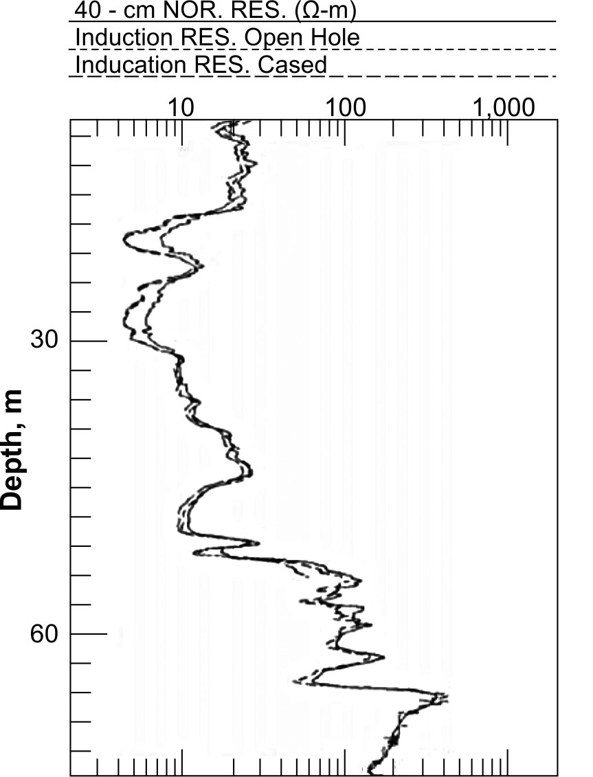
Figure 370. Comparison of open hole induction log with 16-in normal log and induction log
made after casing was installed. (copyright permission granted by Colog, Inc.)
Data Interpretation
The statistical nature of radioactive decay must be considered when running or interpreting nuclear logs. Half-life is the amount of time required for one-half the atoms in a radioactive source to decay to a lower energy state. Half-life of different radioisotopes varies from fractions of a second to millions of years, and it has been accurately measured. In contrast, it is impossible to predict how many atoms will decay or gamma photons will be emitted within the short periods of time in the range of seconds that commonly are used for logging measurements. Photon emission follows a Poisson distribution; the standard deviation is equal to the square root of the number of disintegrations recorded. The accuracy of measurement is greater at high count rates and for a long measuring period. Time constant is an important adjustment on all analog nuclear-recording equipment. Time constant is the time, in seconds, over which the pulses are averaged. Time constant (tc) is defined as the time for the recorded signal level to rise to 63% of the total increase that occurred, or to fall to 37% of the total decrease that occurred. The true value in any radiation field is approached after five time constants, if the probe is still in the same bed that long. If the probe is moving too fast, or if the time constant is too long in thin-bedded materials, the true value never will be recorded before the probe moves out of the layer of interest. The logging speed, count rate being measured, vertical resolution required, and equipment variations have a significant effect on the selection of time constant, so specific values cannot be recommended.
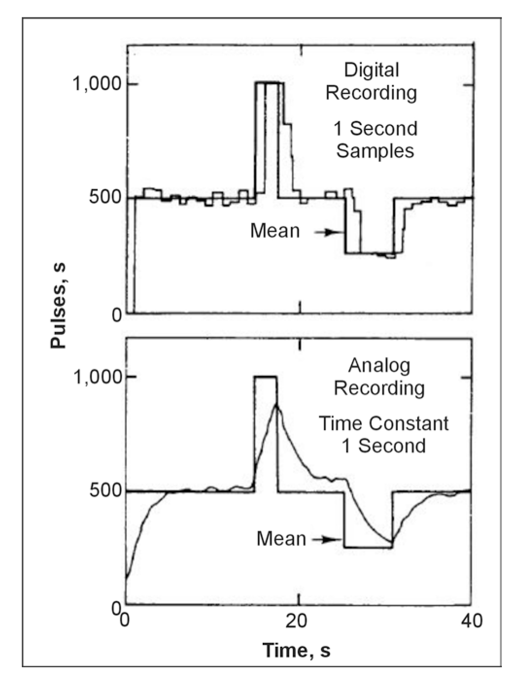
Figure 371. Comparison of a digital recording of a gamma signal with 1-s samples
to an analog
recording with 1-s time constant.
Analog versus digital recording. The difference between an analog recording with a time constant of 1 sec and a digital recording with a sample time of 1 sec is shown in figure 371. Digital recording is gradually replacing analog, but some systems that digitize at the surface still use a time constant circuit to drive an analog recorder. Average or mean radioactivity is shown as the heavier line in figure 371. Note that the digital system changes more rapidly because the time window used does not have a memory like the RC circuit used for time constant in analog measurements. Note also that the analog measurement did not reach the mean value for short time periods. Some commercial logs are recorded at a low sensitivity, long time constant, and high logging speed, so that real changes are small. This results in a smoother curve, and thin beds may not be detected. Bed thickness and lag are additional factors related to the speed at which nuclear logs are run. Lag (L), in feet, is defined as the distance the detector moves during one time constant:
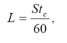 (82)
(82)
where
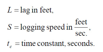
Lithologic Contacts. The contacts between lithologic units on a nuclear log are shifted approximately the amount of lag. Furthermore, beds that are thinner than L are not defined. The general practice for locating lithologic contacts on nuclear logs is to place them at one-half of the maximum log amplitude for a given bed. Thus, if the average count rate for a gamma log in a sandstone was 100 pulses per second (PPS), and the average count rate for a shale was 200 PPS, the contact would be placed at 150 PPS, using the half-amplitude rule. The true depth of the contact would be deeper by the amount of lag. See figure 372 for an illustration of the relation of bed thickness, volume of investigation, and location of contacts for a neutron log. The principles are the same for other types of nuclear logs.
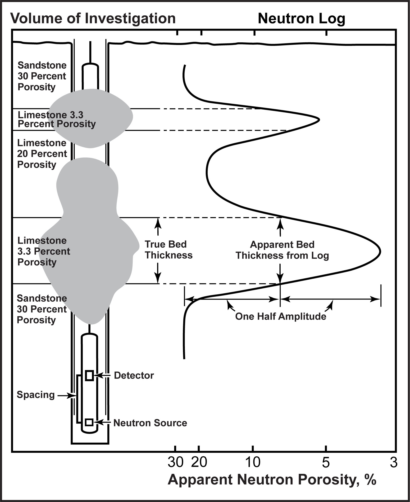
Figure 372. Theoretical response of a neutron probe to changes in porosity and bed thickness.
The shaded area represents the volume of investigation at different probe positions.
Regulation. Use and transportation of radioactive materials is regulated by both Federal and State government agencies. Because of the numerous agencies involved and the frequent changes in regulations, specific information on the subject cannot be provided in this manual. A potential user must consult the appropriate government agency for regulations that apply to the specific type and area of use. The loss of most probes can be prevented if the proper logging procedures are followed. Probes containing radioactive sources need to be the last to be run in an uncased well; they never are run if other probes encounter problems.
Gamma logging
Basic Concept
Gamma logs, also called gamma ray logs or natural-gamma logs, are the most widely used nuclear logs for most applications. The most common use is for identification of lithology and stratigraphic correlation, and for this reason, gamma detectors are often included in multi-parameter logging tools. Gamma logs provide a record of total gamma radiation detected in a borehole and are useful over a very wide range of borehole conditions. The petroleum industry has adopted the American Petroleum Institute (API) gamma ray unit as the standard for scales on gamma logs. The API gamma-ray unit is defined as 1/200 of the difference in deflection of a gamma log between an interval of very low activity in the calibration pit and the interval that contains the same relative concentrations of radioisotopes as an average shale, but approximately twice the total activity. The API gamma calibration pit is located at the University of Houston. The API values of field standards can be determined when that pit is used so that reference values are available when logging. The volume of material investigated by a gamma probe is related to the energy of the radiation measured, the density of the material through which that radiation must pass, and the design of the probe. Under most conditions, 90% of the gamma radiation detected probably originates from material within 150 to 300 mm of the borehole wall.
Data Interpretation
In rocks that are not contaminated by artificial radioisotopes, the most significant naturally occurring gamma-emitting radioisotopes are potassium-40 and daughter products of the uranium- and thorium-decay series. If gamma-emitting artificial radioisotopes have been introduced by man into the groundwater system, they will produce part of the radiation measured, but they cannot be identified unless gamma spectral-logging equipment is used. Average concentrations in 200 shale samples from different locations in the United States indicate that 19% of the radioactivity of shale comes from Potassium-40, 47% from the Uranium series, and 34% from the Thorium series, but these ratios can vary significantly. Only gamma spectral logging can provide the identification and relative concentrations of the natural and man-made radioisotopes that produce the total radioactivity measured by a gamma log. Borehole-gamma spectrometry has considerable application to the monitoring of radioactive waste migration, and it also can provide more diagnostic information on lithology, particularly the identification of clay minerals. Uranium and thorium are concentrated in clay by the processes of adsorption and ion exchange. Some clays are rich in potassium. Fine-grained detrital sediments that contain abundant clay tend to be more radioactive than quartz sands and carbonates, although numerous exceptions to this norm occur. Rocks can be characterized according to their usual gamma intensity, but knowledge of the local geology is needed to identify the numerous exceptions to the classification shown in figure 373. Coal, limestone, and dolomite usually are less radioactive than shale; however, all these rocks can contain deposits of uranium and can be quite radioactive. Basic igneous rocks usually are less radioactive than silicic igneous rocks, but exceptions are known. Several reasons exist for the considerable variability in the radioactivity of rocks. Uranium and thorium are trace elements and are not important in the genesis of rocks. Uranium also is soluble in groundwater under some conditions, so solution, migration, and precipitation may cause redistribution at any time.
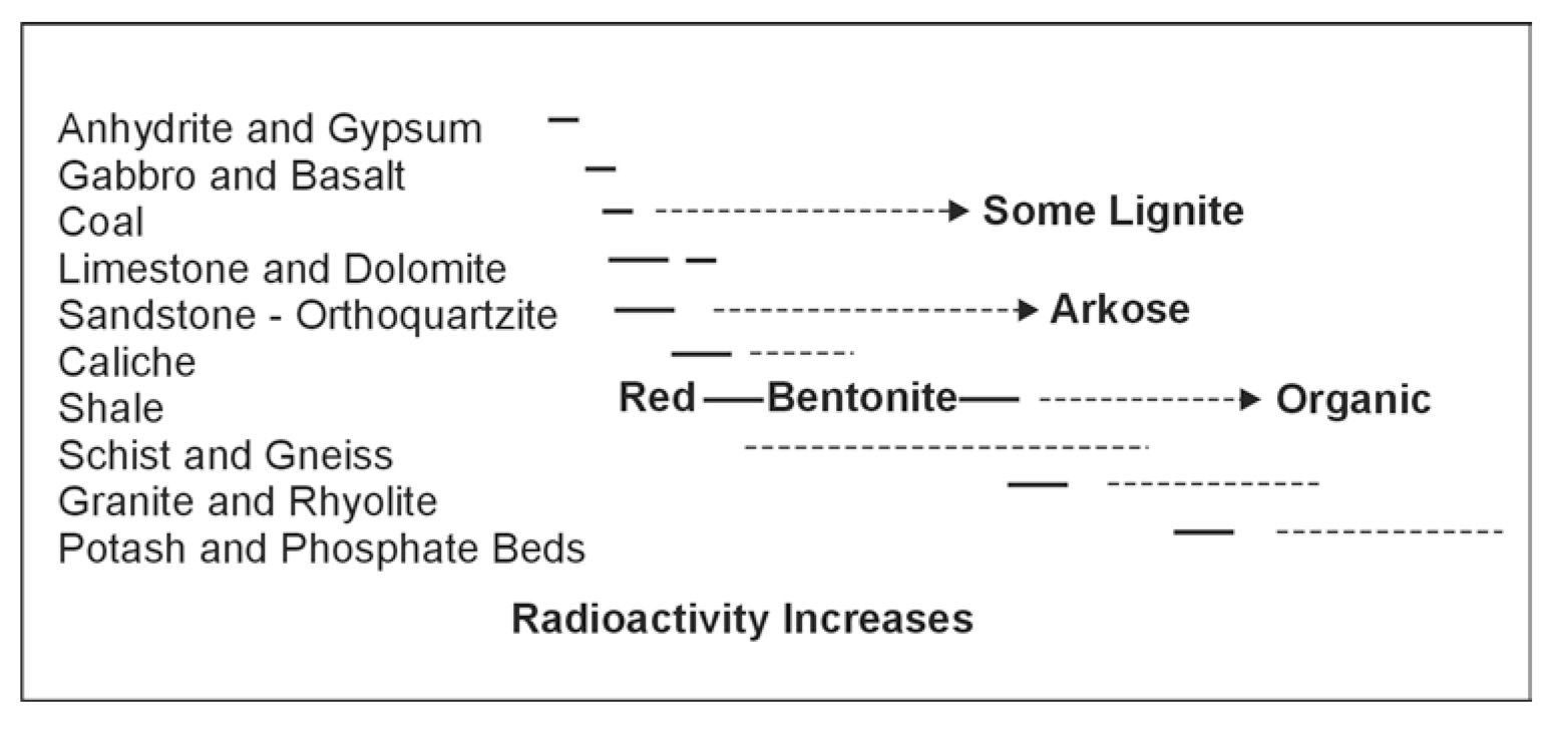
Figure 373. Relative radioactivity of common rocks.
Background Information. Because of frequent variations from the typical response of gamma logs to lithology, some background information on each new area is needed to reduce the possibility of errors in interpretation. Gamma logs are used for correlation of rock units; however, this approach can lead to significant errors without an understanding of their response within the area being studied. For example, gradual lateral change in grain size or increase in arkosic materials in a sandstone may change the response of gamma logs. In igneous rocks, gamma intensity is greater in the silicic rocks, such as granite, than in basic rocks, such as andesite. Orthoclase and biotite are two minerals that contain radioisotopes in igneous rocks; they can contribute to the radioactivity of sedimentary rocks if chemical decomposition has not been too great. Gamma logs are used widely in the petroleum industry to establish the clay or shale content of reservoir rocks. This application also is valid in groundwater studies where laboratory data support such a relation.
Amplitude. The amplitude of gamma-log deflections is changed by any borehole conditions that alter the density of the material through which the gamma photons must pass or the length of the travel path. Thus, casing and cement will reduce the recorded radiation, as will large-diameter wells. The correction factor for water in a borehole as compared to the same borehole filled with air is 1.024 for a 5.72-cm diameter (2.25-in) hole and 1.115, 1.205, and 1.296 for 11.4-, 16.5-, and 21.6-cm (4.5-, 6.5-, and 8.5-in) boreholes, respectively. Correction for steel casing wall thickness varies almost linearly from 1.141 for 0.159 cm (0.0625 in) thickness to 1.891 for 0.953 cm (0.375 in) thickness. The type of borehole fluid has a very minor effect, unless the hole is very large in diameter or the mud contains radioactive clay or sylvite.
Probe Position. The position of a probe in the borehole can have an effect on a gamma log. Most probes are naturally decentralized or running along the borehole wall because of borehole deviation, but if the probe moves to a centralized position, an error is introduced. Changes in gamma-log response over a period of time are not rare. Changes in gamma response in 1 year that apparently were caused by migration of uranium daughter products along fractures have been reported (Keys, 1984).
Gamma-Gamma Logging
Basic Concept
Gamma-gamma logs, also called density logs, are records of the radiation from a gamma source in the probe after it is attenuated and backscattered in the borehole and surrounding rocks. The logs can be calibrated in terms of bulk density under the proper conditions and converted to porosity if grain and fluid density are known. Gamma-gamma probes contain a source of gamma radiation, usually cesium-137 in newer probes, and one or two gamma detectors. Detectors in a gamma-gamma probe are shielded from direct radiation from the source by heavy metal, often lead or a tungsten alloy. Single detector probes, termed "4 pi," are not focused and thus are more affected by borehole parameters. Modern gamma-gamma probes are decentralized and side-collimated with two detectors. Side collimation with heavy metal tends to focus the radiation from the source and to limit the detected radiation to that part of the wall of the hole in contact with the source and detectors. The decentralizing caliper arm also provides a log of hole diameter. Modern tools are called borehole-compensated or borehole-corrected, but they still exhibit some borehole diameter effects. The ratio of the count rates for the near and far detectors is plotted against bulk density, either in the logging equipment, or preferably later so that algorithms can be changed (Scott, 1977). This ratio reduces borehole diameter effects because the near detector has a smaller radius of investigation than the far detector and is thus more affected by changes in diameter. Gamma-gamma logging is based on the principle that the attenuation of gamma radiation, as it passes through the borehole and surrounding rocks, is related to the electron density of those rocks. If a probe detects only radiation resulting from Compton scattering, the count rate will be inversely proportional to the electron density of the material through which the radiation passes. Electron density is approximately proportional to bulk density for most materials that are logged. A correction for the "Z To A" ratio needs to be applied for any minerals that do not have the same ratio of atomic number to atomic mass as the calibration environment. The electron density of water is 1.11 g/cc versus a bulk density of 1 g/cc, and some companies may make this correction. Like other logging systems, calibration of gamma-gamma response is best done in pits designed for that purpose. Calibration can be done in porosity pits like the American Petroleum Institute neutron pit in Houston or in pits maintained by commercial service companies. A set of bulk-density pits is available for free use by anyone at the Denver Federal Center, Denver, CO. Onsite standardization of probe response usually is done with large blocks of aluminum, magnesium, or lucite that are machined with a groove that tightly fits the source and detector section of the probe. The blocks need to be large enough that effects of the environment are minimized, and they need to be located off the ground and away from a logging truck that may contain radioactive sources.
Volume of Investigation. The volume of investigation of a gamma-gamma probe probably has an average radius of 127 to 152 mm; 90% of the pulses recorded originate from within this distance. However, the volume of investigation is a function of many factors. The density of the material being logged and any casing, cement, or mud through which the radiation must pass have a significant effect on the distance gamma photons will travel before being stopped. Within limits, the greater the spacing between source and detector, the larger the volume of investigation. Standoff error is caused when a side-collimated, decentralized probe or skid is separated from the borehole wall by mudcake or wall roughness. According to Scott (1977), standoff errors of 10 mm or more may be corrected accurately using the algorithms he developed.
Data Interpretation
Gamma-gamma logs may be used to distinguish lithologic units and to determine well construction, in addition to determining bulk density, porosity, and moisture content when properly calibrated. The chief use of gamma-gamma logs has been for determining bulk density that can be converted to porosity. Gamma-gamma logs conventionally are recorded with bulk density increasing to the right, which means that porosity increases to the left as it does on conventionally plotted neutron and acoustic velocity logs. Although commercial gamma-gamma logs often have a scale in porosity, the log response is related directly to electron density, which may be related to bulk density by calibration and correction for Z-A errors. The accuracy of bulk-density determinations with these logs is reported by various authors to be from 0.03 to 0.05 g/cc. Figure 374 is a plot of bulk density from laboratory analyses of core versus density log values from a study in Canada (Hoffman, Fenton, and Pawlowica, 1991). It shows how accurate density logs can be under the right conditions. The best results are obtained with gamma-gamma logs in rocks of low bulk density or high porosity. Bulk density can be converted to porosity by the following equation: porosity = grain density minus bulk density divided by grain density minus fluid density. Bulk density may be derived from a calibrated and corrected log. Fluid density is 1 g/cc for most non-petroleum applications, where the rock is saturated. Grain or mineral density may be obtained from most mineralogy texts; grain density is 2.65 g/cc for quartz; 2.71 g/cc commonly is used for limestone, and 2.87 g/cc commonly is used for dolomite. At many sites, gamma-gamma logs provide more accurate porosity data than neutron and acoustic velocity logs. Figure 375 is an example of a comparison of data from the three types of porosity sensing logs versus core data at a Superfund site in Oklahoma (Keys, 1993). Because moisture content affects the bulk density of rocks, gamma-gamma logs can be used to record changes in moisture above the water surface. Thus they can be used in the same way as neutron logs to monitor the downward migration of water from waste disposal or artificial rege ponds.
Well Construction
Gamma-gamma logs can be used to locate cement tops, gravel pack fill-up, or one string of casing outside of another. Gamma-gamma logs for this application are discussed in the section on well completion logs.
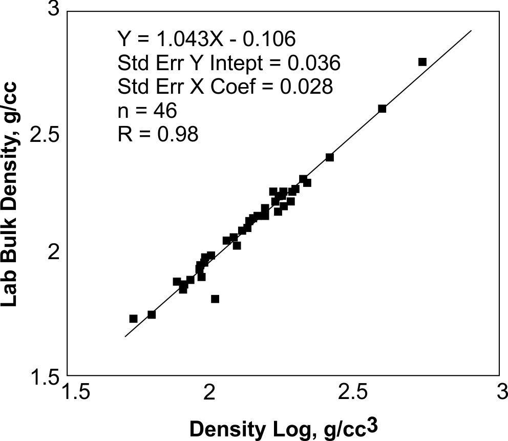
Figure 374. Plot of laboratory measurements of bulk density versus gamma-gamma
log response in the same borehole. (Hoffman, Fenton, and Pawlowicz, 1991;
copyright permission granted by Alberta Research Council)
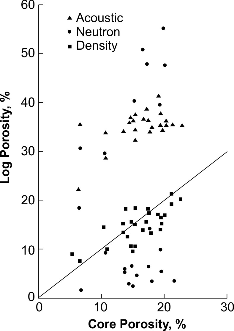
Figure 375. Comparison of laboratory measurements of porosity versus acoustic,
neutron and density log response in the same borehole.
Neutron Logging
Basic Concept
Neutron logs are made with a source of neutrons in the probe and detectors that provide a record of the interactions that occur in the vicinity of the borehole. Most of these neutron interactions are related to the amount of hydrogen present, which, in groundwater environments, is largely a function of the water content of the rocks penetrated by the drill hole. Neutron probes contain a source that emits high-energy neutrons. The most common neutron source used in porosity logging tools is americium-beryllium, in sizes that range from approximately 1 to 25 Curies. Moisture tools may use a source as small as 100 millicuries. Two different neutron-logging techniques are used in groundwater studies: Neutron probes with a large source and long spacing are used for measuring saturated porosity and moisture content in a wide range of borehole diameters; probes with a small source and short spacing are used for measuring moisture content in small-diameter monitoring wells. Three general types of neutron-porosity logs exist: neutron-epithermal neutron, neutron-thermal neutron, and neutron-gamma. Cadmium foil may be used to shield crystal or Helium‑3 detectors from thermal neutrons. Neutron-epithermal neutron logs are least affected by the chemical composition of the rocks logged. Two or more detectors are used in modern neutron tools, and they may be collimated and decentralized by a caliper arm. The ratio of the near to the far detector provides logs that are less affected by borehole parameters than single-detector logs.
Moderating Neutrons. Fast neutrons, emitted by a source, undergo three basic types of reactions with matter in and adjacent to the borehole as they lose energy and ultimately are captured: inelastic scatter, elastic scatter, and absorption or capture. In elastic scatter, the mass of the scattering element controls the loss of energy by the neutron. Light elements are most effective in moderating, or slowing neutrons, whereas heavy elements have little effect on neutron velocity or energy. Hydrogen is the element most effective in moderating neutrons because it has the same mass as a neutron. Because hydrogen is the most effective moderating element, the cloud of epithermal and thermal neutrons occurs closer to the source in rocks with a large hydrogen content than in rocks with a small hydrogen or water content. The moderating and capture processes result in the number of epithermal and thermal neutrons and capture gamma photons being inversely related to the hydrogen content of the rocks, at source-to-detector spacing greater than approximately 300 mm. If detectors are located closer than 300 mm from the source, as in moisture probes, the number of moderated and captured neutrons increases with increasing hydrogen content.
Volume of Investigation. The volume of investigation of a neutron probe is related closely to the content of hydrogen or other strong neutron absorbers in the material surrounding the probe, the spacing between the source and detector, and the energy of the neutrons. In sand with a saturated porosity of 35%, three different types of neutron probes received 90% of the recorded signal within 170, 236, and 262 mm of the borehole wall. In dry rocks, the radius of investigation may be several meters. The reference depth, or point of measurement, on a probe may change somewhat if significant differences in water content are logged. Increasing the source-to-detector spacing increases the volume of investigation in the vertical direction as well as in the horizontal direction, into the rock. This increased volume decreases thin-bed resolution as demonstrated in figure 372. The hypothetical volume of investigation is shown by shading in the figure. Note that size and shape of this volume are shown to change as a function of the porosity as the probe moves up the hole. The log only gives an approximately correct value for porosity and thickness when the volume of investigation is entirely within the bed being logged. Thus, in figure 372, the upper thin limestone bed with 3.3% porosity is indicated by the log to have a much higher porosity and greater apparent thickness than the lower bed with a porosity of 3.3%. The usual technique for determining bed thickness from any type of nuclear log is to make the measurement at one-half the maximum amplitude of the deflection that represents that bed, as shown on the figure.
Data Acquisition
Calibration of all neutron-logging systems used in the petroleum industry is based on the API calibration pit in Houston, Texas. The pit contains quarried limestone blocks that have average porosities of 1.884%, 19.23%, and 26.63%. These values have been rounded by the American Petroleum Institute to 1.9%, 19%, and 26%, and the 19% block has been assigned the value of 1,000 API neutron units (Belknap, et al., 1959). Figure 376 shows calibration data for a compensated neutron probe in the API pit (Keys, 1990). Although the API pit is the widely accepted primary standard, it is only valid for limestone, so that most large logging companies maintain their own calibration facilities for other rock types, like dolomite and sandstone. Careful evaluation of laboratory analyses of core samples may lead to a valid calibration, but scatter of data points is to be expected. Regardless of how primary calibration is carried out, field standardization must be done at the time of calibration and frequently during logging operations. The most practical field standards permit the checking of probe response with the source installed in a reproducible environment that has a high hydrogen content. Although a plastic sleeve may be used, it must be quite heavy to be large enough to cover both source and detectors and thick enough to reduce outside effects.
Data Interpretation
In many rocks, the hydrogen content is related to the amount of water in the pore spaces. This relation is affected by the chemical composition of the water, hydrogen in some minerals and bound water in shales. Neutron logs are affected by many of the same borehole parameters that affect gamma-gamma logs, although usually to a lesser degree. These extraneous effects include borehole diameter, mud cake or stand off, salinity of the borehole and interstitial fluids, mud weight, thickness of casing and cement, temperature and pressure, and elemental composition of the rock matrix. Matrix effects are considered part of the interpretation process and may be analyzed by cross-plotting techniques, as illustrated in the General In-hole Logging Procedures section. Casing does not cause a major shift on most neutron logs, as it typically does on a gamma-gamma log. Neutron logs run through drill stem do not show the location of collars as a gamma-gamma log does. Plastic pipe of constant thickness merely causes a shift in log response similar to, but of lower magnitude than that caused by the water level in a small-diameter well. The short spacing used in moisture probes reduces the volume of investigation, so that borehole effects are increased. For this reason, boreholes to be used for logging with a moisture probe need to be drilled as small as possible. The annular space between casing and borehole wall also needs to be small, and the probe needs to fit the casing tightly. Neutron logs are most suitable for detecting small changes in porosity at low porosities; gamma-gamma logs are more sensitive to small changes at high porosities. Although the interpretation of neutron logs for porosity and moisture content are stressed as primary applications, much use has been made of the logs for determining lithology. Like gamma logs, they can be used for lithology and stratigraphic correlation over a wide range of borehole conditions.
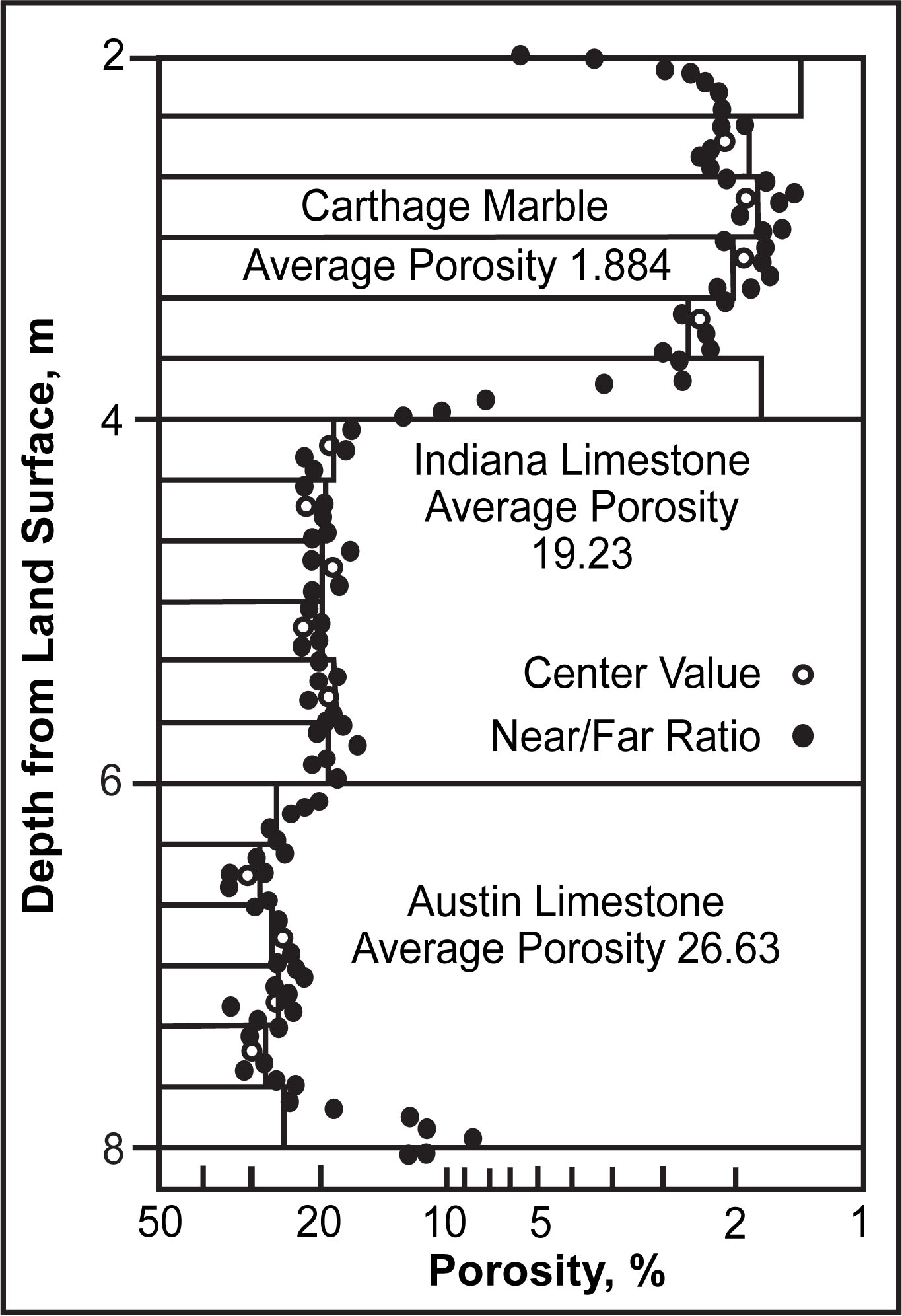
Figure 376. Calibration data for a compensated neutron-porosity probe in the API limestone pit.
Applications
Neutron-activation logging has potential for application to groundwater quality problems, because this technique permits the remote identification of elements present in the borehole and adjacent rocks under a wide variety of borehole conditions. Neutron activation produces radioisotopes from stable isotopes; the parent or stable isotope may be identified by the energy of the gamma radiation emitted and its half-life, using a gamma spectral probe (Keys and Boulogne, 1969).