Crosshole Sonic Logging (CSL)
The Crosshole Sonic Logging (CSL) method is developed for integrity testing of concrete foundations, such as drilled shafts, slurry walls, and auger cast piles. This cross-hole logging technique is performed using water-filled PVC or steel access tube pairs.
Basic Concept: Crosshole Sonic Logging (CSL) uses high frequency compressional sonic waves as the energy source. The sonic source produces an impulse whose frequency content is usually 30 to 40 kHz. Sonic waves passing through concrete are influenced by the density and elastic modulus of the concrete. Fractured or "weak" concrete zones lower the velocity of the sonic waves and, therefore, can be detected. In addition, the amplitude of a seismic pulse is affected by these defects although this is not extensively used at the present time. The frequency content of the seismic energy pulse determines the resolution and penetration of the signal. High frequencies have high amplitude attenuation but can image small targets. Conversely, lower frequencies have less attenuation but image larger targets.
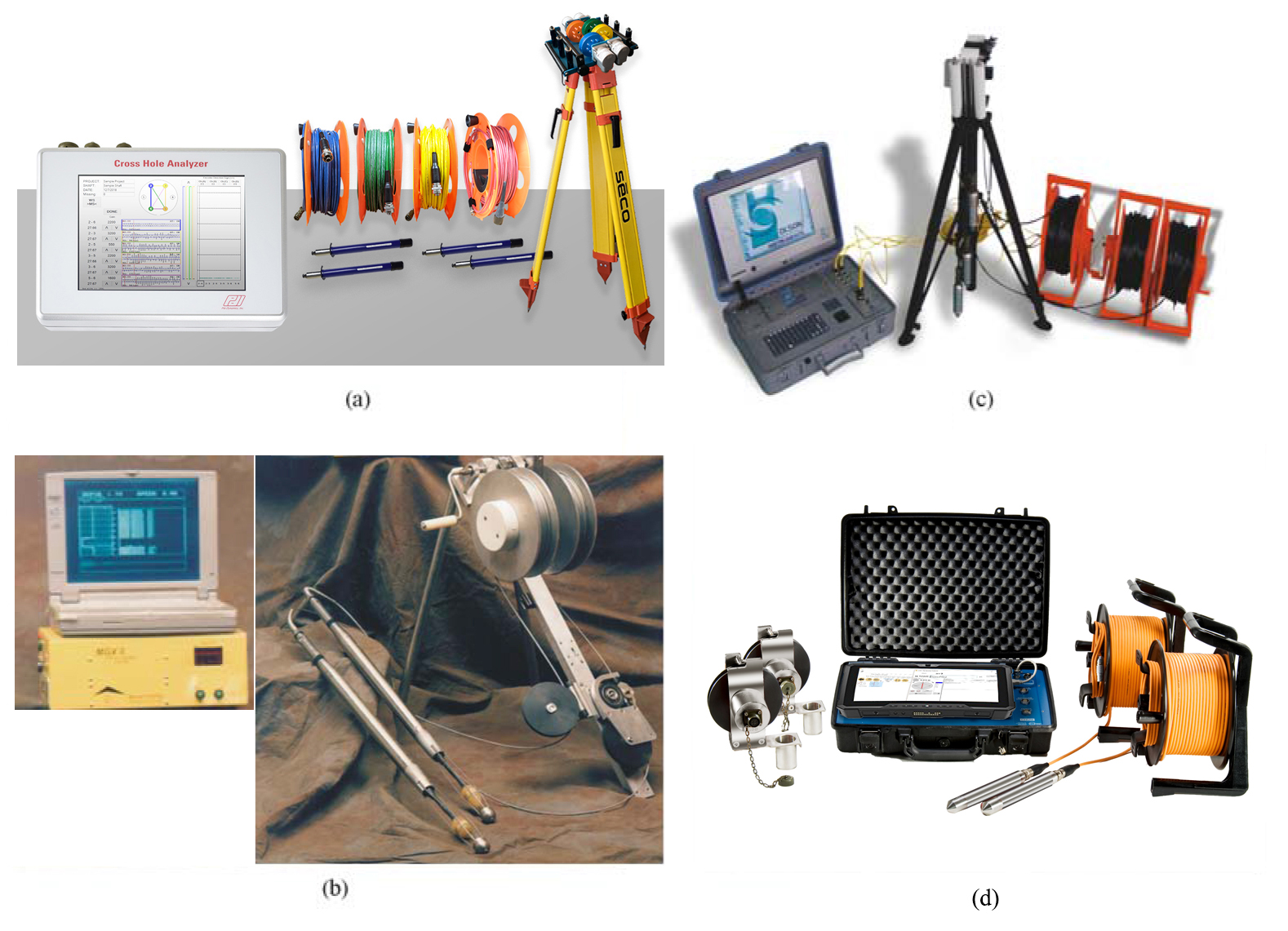
Figure 18. Crosshole Sonic Logging Instruments.
(a) Pile Dynamic, Inc., (b) Mt. Sopris Instruments,
(c) Olson Instruments, Inc., and (d) PileTest, Inc.
Several companies manufacture instruments for the CSL system; three sets of such system are shown in Figure 18.
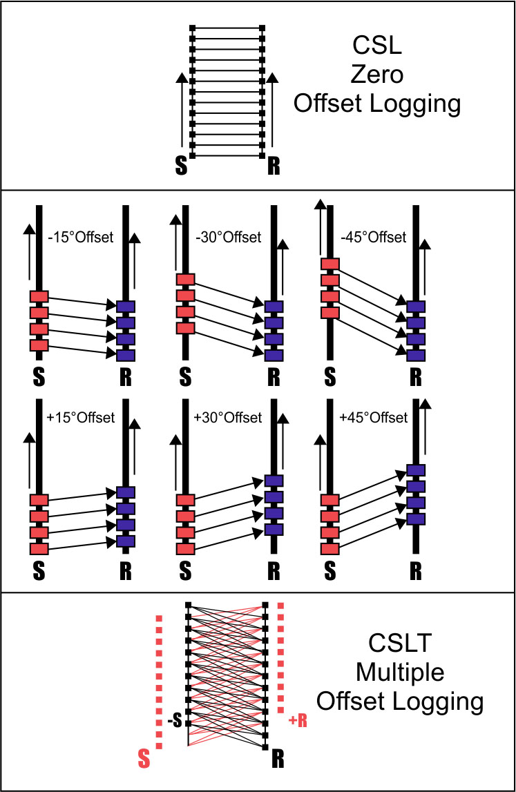
Data Acquisition: Figure 19 illustrates the CSL method. Steel or PVC access tubes must be attached to the inside of the reinforcing rebar cage prior to the concrete placement and be filled with water. At least two schedule 40 access tubes, usually having a inside diameter of 50 mm, are required. Special care must be taken when installing access tubes to avoid debonding between the concrete and the tubes. Poor bonding between access tubes and concrete can cause complete signal loss. One of the tubes is used for the transmitter and the other for the receiver probe. The transmitter and receiver probes can be oriented such that the path between them is horizontal (zero offset, as seen in figures 19 and 21) or with some offset. Zero offset logging is called standard Crosshole Sonic Logging. Readings are taken at regular 6 cm intervals down the shaft while maintaining the same offset. Defects are observed as an increase in the travel time of the seismic wave from the transmitter to the receiver. It is important that the tubes are vertical, and that the distance between them is constant for their entire length so that seismic travel time differences do not result from these distance differences rather than defects in the concrete. In addition, unrecognized distance differences in the distance between tubes may result in false interpretations of defects.
Other variations in the geometric configuration are also used. These include the source and receiver lowered into the same tube, or a source and multiple receivers lowered into separate holes. The most commonly used configuration is the one described above.
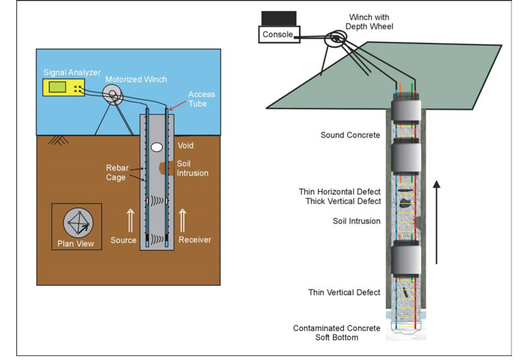
Figure 19. Crosshole Sonic Logging method with various kinds of defects. (Blackhawk GeoServices, Inc.)
Figure 19 shows the CSL method and the ray paths. Common defects are also shown illustrating their influence on the seismic wave travel times.
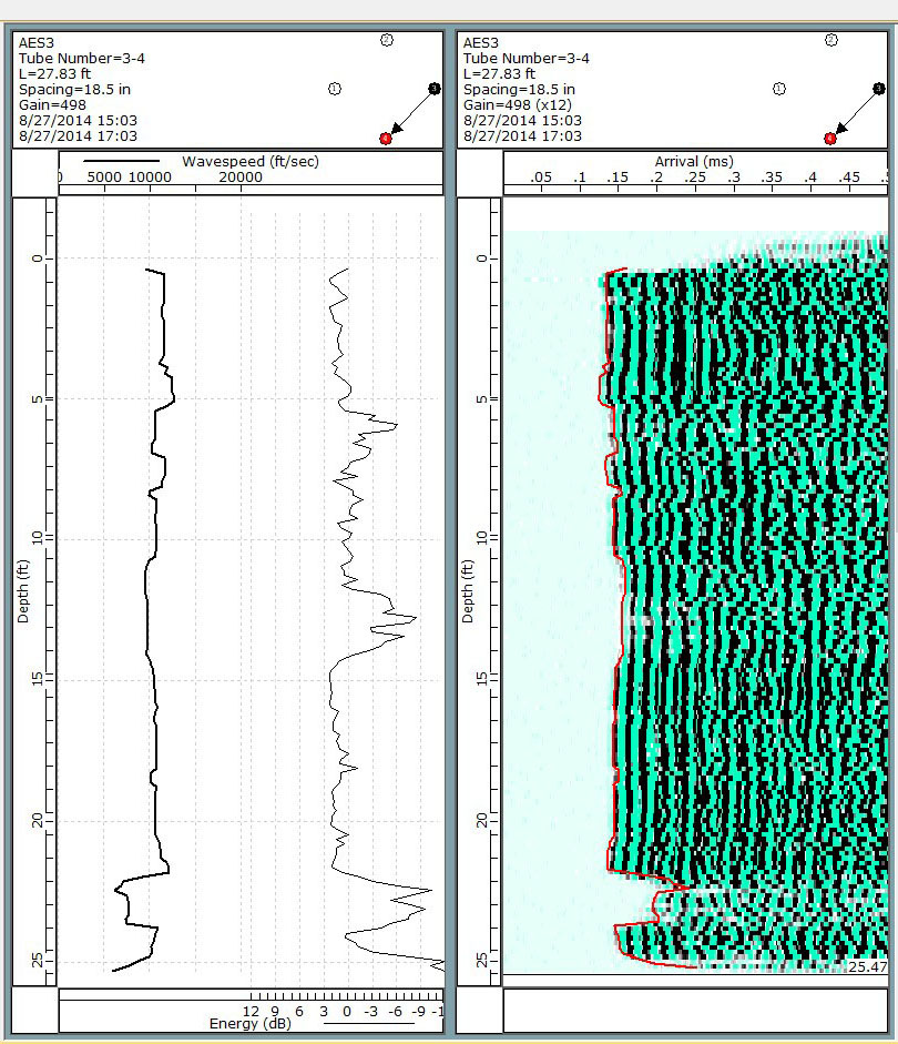
Data Processing: The received data must plotted and presented such that any defects in the shaft are clearly observed. Figure 20 shows a typical CSL travel time plot. If only two access tubes are available and only one offset between the transmitter and receiver is used, then anomalies may exist anywhere between the two tubes. It is then difficult to determine the geometry and exact location of the anomaly with respect to the tube location. However, if data are collected with several different offsets between the transmitter and receiver, then a more definitive location can be given for any anomalies.
Advantages: CSL allows for accurate Characterization of soil intrusions or other anomalies throughout the shaft inside the rebar cage (between the tubes). Several levels of defects can be detected by this method with high precision. It can be used to identify young (heavy retarded) un-cured concrete.
Limitations: Access tubes must be installed, usually on the reinforcing cage, prior to concrete placement, and special care must be taken to avoid debonding between the concrete and the tubes. No signal will be obtained in the debonded zone. Debonding can be caused by grease, oil, or other contaminant on the outer surface of the tubes, or by mechanical shock before the concrete has gained significant strength. Probably the most common cause of debonding is thermal shock, caused by topping up the tubes with cold water when the concrete temperature is still elevated by the heat of hydration.
CSL testing will only detect anomalies along the pulse path between tubes. It cannot reliably detect anomalies outside the reinforcing cage, and will not identify bulbing (increase in diameter), although this can often be checked by the Sonic Echo (SE)/Impulse Response (IR) tests, as described in Sonic Echo/Impluse Response, depending on the shaft's length/diameter (l/d) ratio.
Crosshole Sonic Logging Tomography (CSLT)
Tomography is an inversion procedure that provides two- or three-dimensional (2-D and 3-D) velocity (and/or attenuation) images between access tubes from the observation of transmitted first arrival energy. This method can be used for delineating internal flaws in man-made structures; such as buildings, bridges, slurry diaphragm walls, and dams.
Basic Concept: Tomography data collection involves scanning the region of interest with many combinations of source and receiver depth locations. Typical field operation consists of holding the receiver tool at the bottom of one hole/surface and moving the source tool systematically in the opposite hole/surface from bottom to the top. The receiver is then moved to the next depth location and the test procedure is repeated until all possible source-receiver combinations are incorporated.
Data Acquisition: Offset-Tomography (CSLT shown in figure 21) consists of running a zero-offset (CSL) log in combination with several positive offset (receiver is shallower) and negative offset (source is shallower) logs to create a two-dimensional tomographic panel between a pair of tubes. This procedure is repeated for all possible inspection tube combinations to form a three-dimensional tomography dataset.
Data Processing: In the tomographic inversion technique, the acoustic wavefield is initially propagated through a presumed theoretical model and a set of travel times are obtained by ray-tracing (forward modeling). The travel time equations are then inverted iteratively in order to reduce the root mean square (RMS) error between the observed and computed travel times. The inversion results can be used for imaging the velocity (travel time tomography) and attenuation (amplitude tomography) distribution between boreholes.
Data Interpretation: Figure 22 illustrates the results of a CSL survey compared to a CSLT survey. The two drawings on the left side of the figure show the ray paths for the CSL and CSLT systems. The third drawing shows the location of the defects in the shaft, and the fourth drawing illustrates the results of the CSL survey. As can be seen, the top and bottom of the defect are observed. However, it is not possible to identify the exact location of the defect from the CSL data. With CSLT 2-D and 3-D tomographic images, it is possible to provide a more accurate volumetric definition of the defect zones within the shaft than the CSL method.
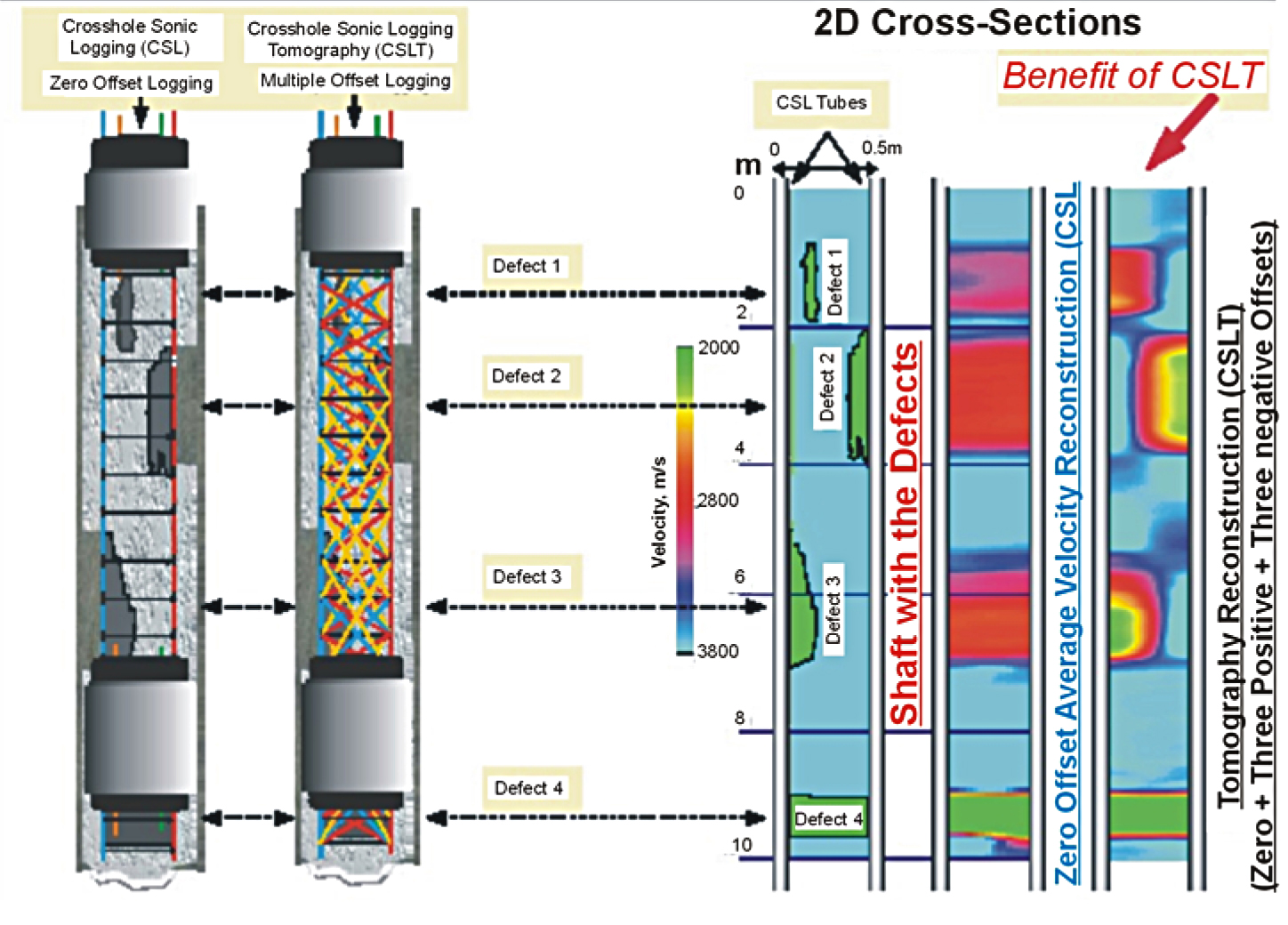
Figure 22. Comparison of Crosshole Sonic Logging and Crosshole Sonic Logging Tomography
results.
(Blackhawk GeoServices, Inc.)
Advantages: CSLT Provides for two-dimensional area or three-dimensional volumetric imaging of defect zones for immediate engineering remediation. Tomography is used in before and after surveys for monitoring the effectiveness of remediation. Tomographic processing can identify horizontally elongated defects, such as cold joints, that are missed by standard CSL technique (amplitude or travel time). Attenuation tomography can be used for delineating fracture zones.
There are three main benefits of tomographic imaging:
- Tomographic imaging provides better spatial resolution of defects for confirmation through coring followed by remedial action;
- Where compressive strength data from core samples is available, Tomography can provide a more accurate correlation between percentage drop in velocity with percentage drop in concrete strength for shaft acceptance decisions;
- Where anomalous CSL data have been recorded, two- and three-dimensional tomography can provide owner's engineers with a tool for assessing the integrity and acceptability of drilled shaft foundations without further costly delays to construction.
Limitations: Tomography is data-intensive for non-automated CSL field systems. Specialized 3-D analyses software is required for true three-dimensional imaging. Artifacts can be present due to limited ray coverage near the image boundaries.
Depending on the vertical offsets used, Tomography may not provide useful data within about one shaft diameter of the top or bottom of a foundation shaft.
Currently this method cannot be used to image defects outside the rebar cage.
Gamma-gamma Density Logging (GDL)
The 4-pi Gamma-Gamma Density Logging (GDL) method is developed for integrity testing of concrete foundations, such as drilled shafts, slurry walls, and auger cast piles. This single-hole logging technique is performed using air or water-filled PVC or steel access tubes.
Basic Concept: The technique is able to detect drops in average bulk density that is indicative of anomalies in the material surrounding the inspection tube. The gamma-gamma logger measures the intensity of reflected radiation, or backscatter, from the material around the borehole. The intensity of the backscatter is largely a function of the density of the material. Variations in backscatter intensity, therefore, indicate variations in density. The method is used for QA of concrete in large-diameter caissons and mass concrete foundations where access tubes can be installed with the reinforcing cage before the concrete is placed. Figure 23 shows the equipment used for gamma-gamma logging.

Figure 23. Gamma-gamma denisty logging equipment. (AMEC Earth & Environmental, Inc.)
Current gamma-gamma logging equipment is based on lightweight geophysical logging systems that use a laptop computer for computer control, data acquisition, and storage. One person can operate this equipment.
The gamma-gamma log can be used as a comparative form of testing, where variations in backscatter intensity indicate anomalies in concrete quality. If the anomalies must be quantified, or actual density values are required, the gamma backscatter values must be correlated with a reference density value. For calibration purposes, a test block should be constructed of the same concrete, with an access tube of the same material as those used in the structure to be tested. Gamma-gamma tests performed under controlled conditions on the test block then provide reference measurements from which a factor can be calculated that will relate gamma intensity to density.
Data Acquisition: In the GDL test method, a weak Cesium-137 source is used to emit gamma rays into the surrounding material. A small fraction of the gamma ray photons are reflected back to the probe (due to compton scattering) and their intensity is recorded by a NaI scintillation crystal as counts per second (cps). The measured count rate (cps) depends on the electron density of the surrounding medium which is proportional to the mass per unit volume. The tool is calibrated by placing the probe in an environment of known density in order to convert the measured count rate (cps) into the units of density in gr/cm3 or lbs/ft3.
In the GDL test, the radius of investigation is largely governed by ½ of the source-detector spacing. An optimal spacing is selected (generally about 35 cm) and the GDL test is performed from all tubes in order to obtain uniform coverage around the perimeter of the shaft. Good concrete condition will result in a near continuous alignment of the data. Anomalous zones-due to soil intrusions, poor concrete, or voids-are characterized by large low density (high count rate) deflection in the data.
Gamma-gamma logs can be conducted in water or air-filled access tubes made of either PVC or steel, provided that the probe is recalibrated for the specific tube material, and the presence or absence of water. Gamma-gamma logs are not sensitive to the quality of the bond between the access tubes and the concrete, and will still provide usable data even if the tube is completely debonded from the concrete.
Data Processing: Data processing is conducted with a microcomputer similar to that used for acquisition. The data are usually processed for bulk density. These calculations are performed during real-time data acquisition or post-acquisition with a software analysis package.
Data Interpretation: Figure 24 shows the data and exposed upper portion of a shaft.
In figure 24, the data from Tube 1 (left trace) indicated possible flaws in the upper 3 m of the shaft. Excavation of the top of the shaft at Tube 1 revealed rebar without proper concrete cover. Very low readings of 2,306 to 2,403 kg/m3 in the upper 30 to 60 cm of Tube 1 were corroborated by an absence of concrete along that tube at the upper four horizontal rebars. Concrete was present for the next few meter as was indicated by density readings between 2,419 and 2,451 kg/m3. Measured densities then dropped down from 2,419 kg/m3 to 2,322 kg/m3 at depths of about 1.5 to 3 m. The picture shows that neither Tube 1 nor the horizontal rebar in this area were covered by concrete.
Advantages: GDL allows for precise Characterization of soil intrusions or other anomalies at a radius of about 18 cm both inside and outside of the rebar cage. It can be used in fresh concrete while restoration is still feasible as the density of concrete changes minimally as it sets. GDL can provide information related to the quality of the concrete. The tube debonding condition minimally affects the GDL data.
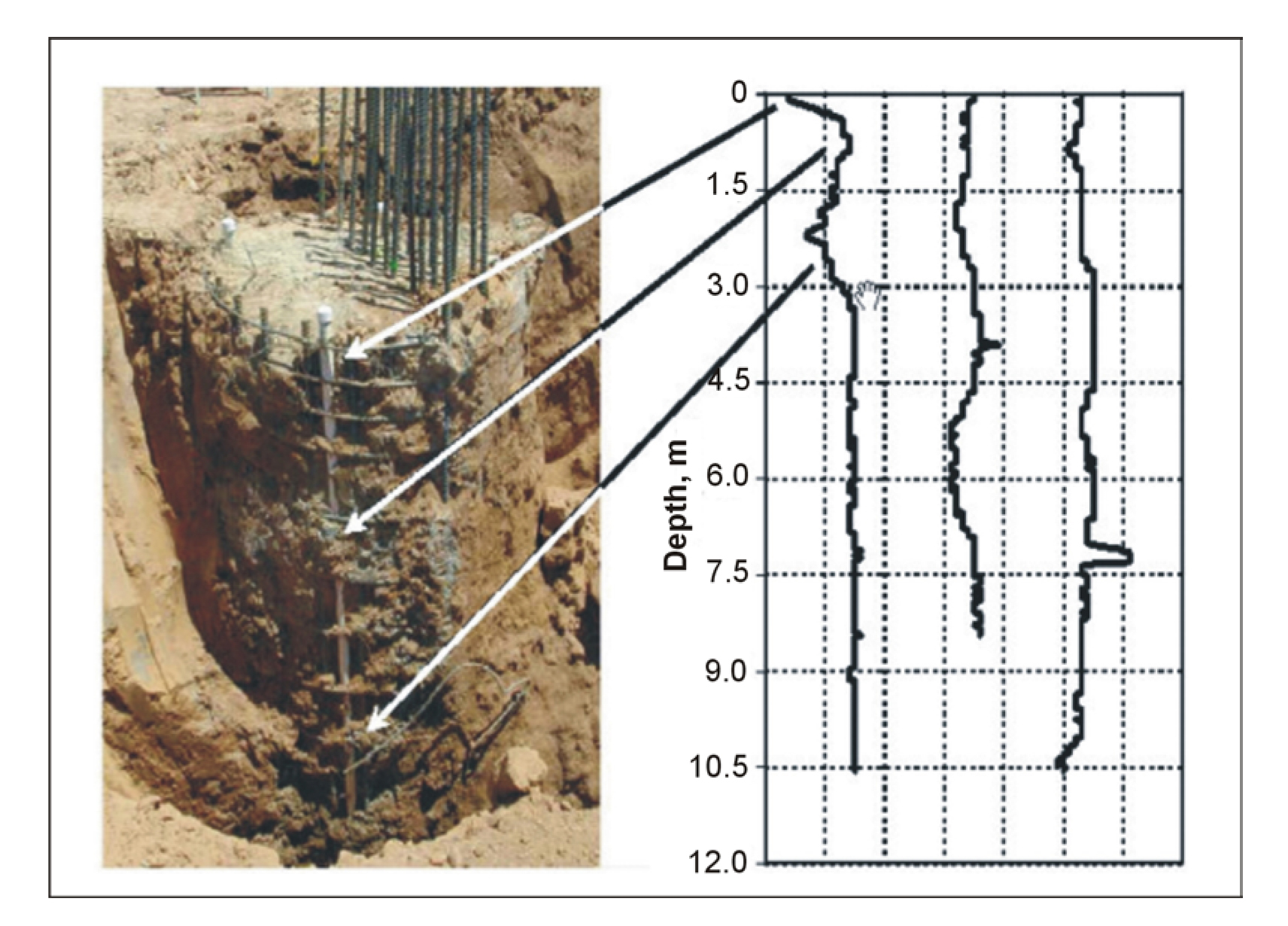
Figure 24. Gamma-gamma density logs and results. (Geophysics, 2002)
Limitations: GDL cannot be used to detect anomalies inside the shafts, only along the outer perimeter of the shaft at about 18 cm radius from each tube or 36 cm tube-tube spacing. It can not be used to identify young, heavily-retarded uncured concrete. GDL cannot detect shaft bulbing (increase in diameter). GDL requires special handling for the use of radioactive sources. As mentioned above, an obvious limitation of the method is the limited depth of penetration. Generally, with the gamma-gamma method, the location of the defect within the shaft cannot be determined, only its existence and depth. Combining the CSL/CSLT methods with the gamma-gamma density method provides a good solution.
Sonic Echo/Impulse Response (SE/IR)
Sonic Echo/Impulse Response (SE/IR) tests are performed to evaluate the integrity and determine the length of deep foundations. These methods can be used to detect defects, soil inclusions and pile necking, diameter increases (bulbing) as well as estimate approximate pile lengths.
SE/IR tests are commonly performed on concrete drilled shafts and driven piles (concrete or timber) or auger-cast piles. The test can also be performed on shallow wall structures such as an abutment or a wall pier of a bridge provided the top of the wall is accessible.
Basic Concepts: These tests are often incorrectly described as being different data analysis procedures for data acquired by the same method i.e., that the Sonic Echo method requires only a measurement of the travel time of seismic waves (time domain) generated by a hammer impact, and the Impulse Response method uses spectral analysis (frequency domain) of the time domain data for interpretation. Although this procedure does provide some limited information, the true Impulse Response method requires measurement of the force of the hammer impact. In addition, the motion sensor in typical SE systems is an accelerometer, whereas in the IR system, is it a geophone velocity transducer.
Both methods are sometimes referred to as Pile Integrity Test methods (PIT). Further confusion sometimes occurs because the Sonic Echo method is also known as Echo, Seismic, Sonic, Impulse Echo, and Pulse Echo. Other names for the Impulse Response method include Sonic Mobility, Transient Dynamic Response, Impulse Response Spectrum, Impedance, Shock, and Transient Response.
Both the SE and the IR tests record the reflection of compressional waves (also called P waves by geophysicists) from either the bottom of the foundation element being tested, or from changes in impedance caused by a crack, soil inclusion, or change in diameter. The wave is generated by striking the top of the foundation with an impulse hammer. The wave propagates down through the foundation until it encounters a change in acoustic impedance, which reflects some or all of the wave energy back up to the top of the foundation, where it is detected by a motion transducer, or receiver. For the IR test, the hammer is instrumented with a transducer to also measure the force of the impact.
Data Acquisition: For drilled shafts and piles, the best results from SE/IR tests are obtained if the top of the drilled shaft or the pile is exposed to allow receiver attachment and hammer strikes (see figure 25a). If the top is not exposed, then the SE/IR tests are performed on the side that provides at least the upper 30 to 60 cm of the shaft be exposed (see figure 25b). In those cases where the superstructure is in place, the SE/IR data becomes more difficult to interpret because of the many reflecting boundaries, and two or more receivers should be used to track reflections (please refer to the Ultraseismic method in Ultraseismic (US) Profiling).
In an SE/IR test, a hammer strikes the foundation top, and a receiver monitors the response of the foundation. A digital analyzer records the hammer input and the receiver output. SE tests are typically performed with different frequency filtering to optimize reflections coming from the bottom of the foundation and to reduce the effect of surface waves or reflections from a discontinuity at a shallow depth where the frequencies associated with these two conditions are high. In an IR test, a digital analyzer automatically calculates the transfer and coherence functions after transforming the time records of the hammer force sensor and the receiver to the frequency domain.
Data Processing: To help interpret SE/IR data, processing techniques can be applied to enhance weak echoes. SE signals, which are measurements of acceleration, are commonly integrated to produce velocity and treated with a gain function that increases exponentially with travel time from the source to enhance weak reflections and to compensate for the damping of energy. For cases where echoes are not easily seen in the data, other sophisticated signal processing techniques are available. In simple cases, the SE data can be used to obtain an image of the shaft through a process called impedance imaging.
For best results, it is important to know the P-wave velocity through the concrete being tested. It is not safe to assume the P-wave velocity is known from other empirical data. The P-wave velocity is a function of concrete density and elastic modulus. Therefore, velocities can vary depending on the aggregate used, age of the structure, and state of weathering, Alkali Aggregate Reaction (AAR) or other degradation. It is easy to measure local velocity if two sides of the structure are available or if an exposed section of the body of sufficient length is available. A source placed a measured distance from a receiver can be used to get a first arrival signal to compute the P-wave velocity.
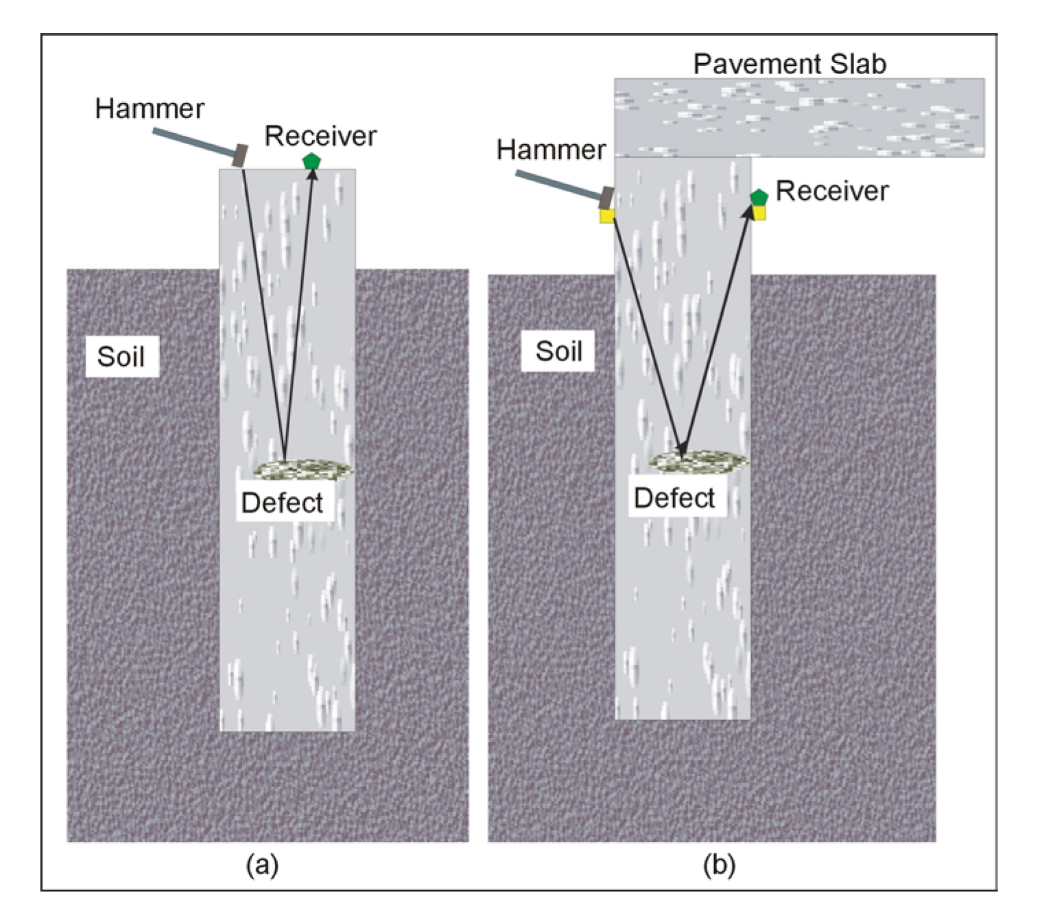
Figure 25. Defects in shafts and seismic waves used to image these defects.
Data Interpretation: Sonic Echo data are used to determine the depth of the foundation based on the time separation between the hammer impact and the first reflection events or between any two consecutive reflection events (Dt) according to the following equation:
 (3)
(3)
where D is the reflector depth, and V is the velocity of compressional waves. Figure 26 shows a sonic echo record and the depth calculation using the second and third echoes. The multiple echoes are all interpreted as coming from the same reflector since they are an equal time apart on the record. Any pair can be used to calculate the two-way travel time between the source and the reflector. In this case the clearest pair of echoes were the second and third, which were used to calculate the depth using the formula above, giving a depth of 2.01 m. A reflector can be the bottom of the foundation or any discontinuity along the embedded part of the foundation. Sonic Echo data can also be used to determine the existence of a bulb or a neck in a shaft or the end conditions of the shaft based on the polarity of the reflection events.
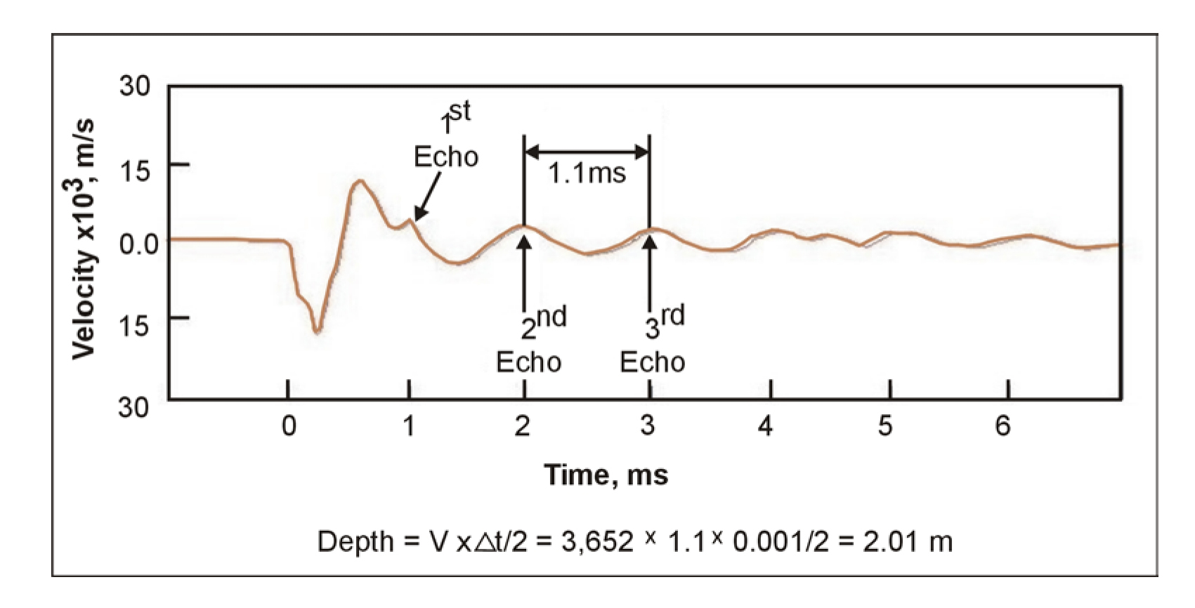
Figure 26. Sonic Echo record and depth calculation.
Impulse Response data are used to determine the depth of reflectors according to the following equation:
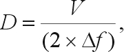 (4)
(4)
where V is velocity and Df is the distance between two adjacent peaks in the transfer function plot. The multiple echoes from a discontinuity or bottom, as seen in the Sonic Echo method, result in increased energy at the frequency of the echo. This causes a series of harmonic peaks in the frequency spectrum. Using the frequency difference between harmonic peaks (Df) in the formula above gives the depth of the structure. IR data also provide information about the dynamic stiffness of the foundation. This value can be used to predict foundation behavior under working loads or correlated with the results of load tests to more accurately predict foundation settlement.
Example data for the Impulse Response method is shown in Figure 3, along with the depth calculation results showing a reflector depth of 8.7 m, assuming a P-Wave velocity of 4,000 m/s.
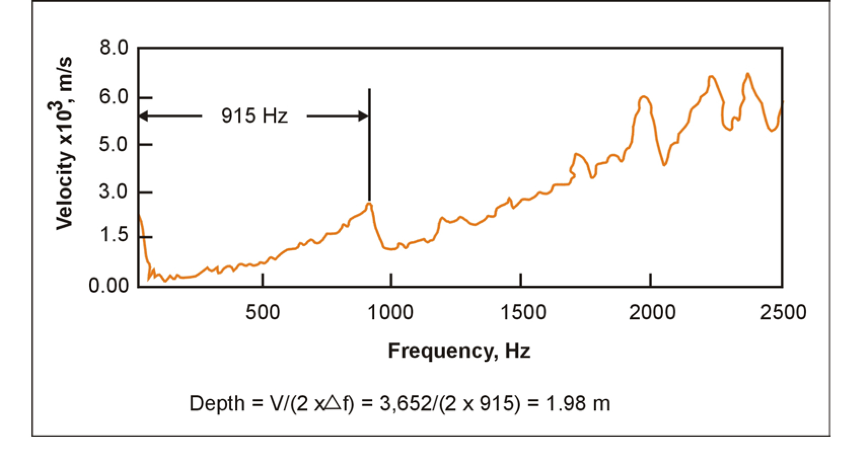
Figure 27. Depth calculations using frequency domain data for the Impulse Response method.
Advantages: These are quick and economical test methods used mostly in columnar shaped foundations without access tubes. Evidence of flaws can be found and evaluated early, with minimal delays to construction.
Limitations: The SE/IR methods work best for free-standing columnar-shaped foundations, such as piles and drilled shafts, without any structure on top.
Typically, SE/IR tests are performed on shafts or piles of length-to-diameter ratios of up to 30:1. Higher ratios (45:1) are possible in softer soils. The method can only detect large defects with cross-sectional area change of greater than 5%.
A toe reflection is usually not detectable if the pile is socketed in bedrock of similar stiffness (or acoustic impedance) as concrete. If the pile is embedded in very stiff soils, penetration may be limited to about 20 diameters. For the softer soils, echoes have been observed in piles with length diameter ratios of more than 55:1. This method is usually not effective on steel H-piles.
A much more detailed analysis, with detection of much smaller defects, can be done using Crosshole Seismic Logging (CSL), gamma-gamma density logging (GDL), and Crosshole Seismic Tomography (CSLT).
Single Hole Sonic Logging (SSL)
The single hole sonic logging (SSL) method is developed for integrity testing of concrete foundations in water-filled PVC or steel access tubes.
Basic Concept: The single hole sonic logging (SSL) method measures the speed of a sonic pulse around a single water-filled access tube to provide quality assurance of concrete placement. The method is particularly suited to small-diameter piles that penetrate rockfill with large cavities and are then socketed into rock. It is also suitable for small- diameter piles where the installation of two tubes may be impractical. The method can also be used to confirm CSL defects and for confirmation of debonded conditions between an access tube and the surrounding concrete. The probe consists of a transmitter and a receiver, as illustrated in figure 28.
Data Acquisition: A single water-filled tube is required for the instrument. Similar to sonic logging in boreholes, this method measures the refracted arrival time between a sonic transmitter and receiver probe as a function of logging depth interval of typically 6 cm.
Generally, the method should be run after the concrete has been allowed to set for about six days. As reported by J.M. Amir in the piletest.com website, this method was tested in both steel and PVC-cased tubes and it was found that the PVC tube worked best. The steel tube prevented the wave from exiting the tube because of its high velocity. Tube diameter was also investigated using two tubes having diameters of 40 and 50 mm. It was found that the smaller tube filters noise more effectively and facilitates processing of the signal. In investigating probe separation, it was found that increasing the probe separation enhanced the anomaly. As expected, the detection range for the system depends on the size of the defect. A 50% reduction in signal may be observed even when the defect is only 30 mm high, providing it surrounds the tube.
Advantages: The method can be used to confirm CSL defects and for confirmation of debonded conditions between an access tube and the surrounding concrete.
Limitations: Access tubes must be installed prior to concrete placement and special care must be taken to avoid tube debonding between concrete and the tubes. No signal is obtained in the tube debonding zone.
SSL can only detect defects within centimeters of the access tubes. SSL does not define the depth extent of anomalies as accurately as CSL. It cannot be used to detect shaft bulbing (increase in diameter); although this can easily be checked by the Sonic Echo (SE)/Impulse Response (IR) test.
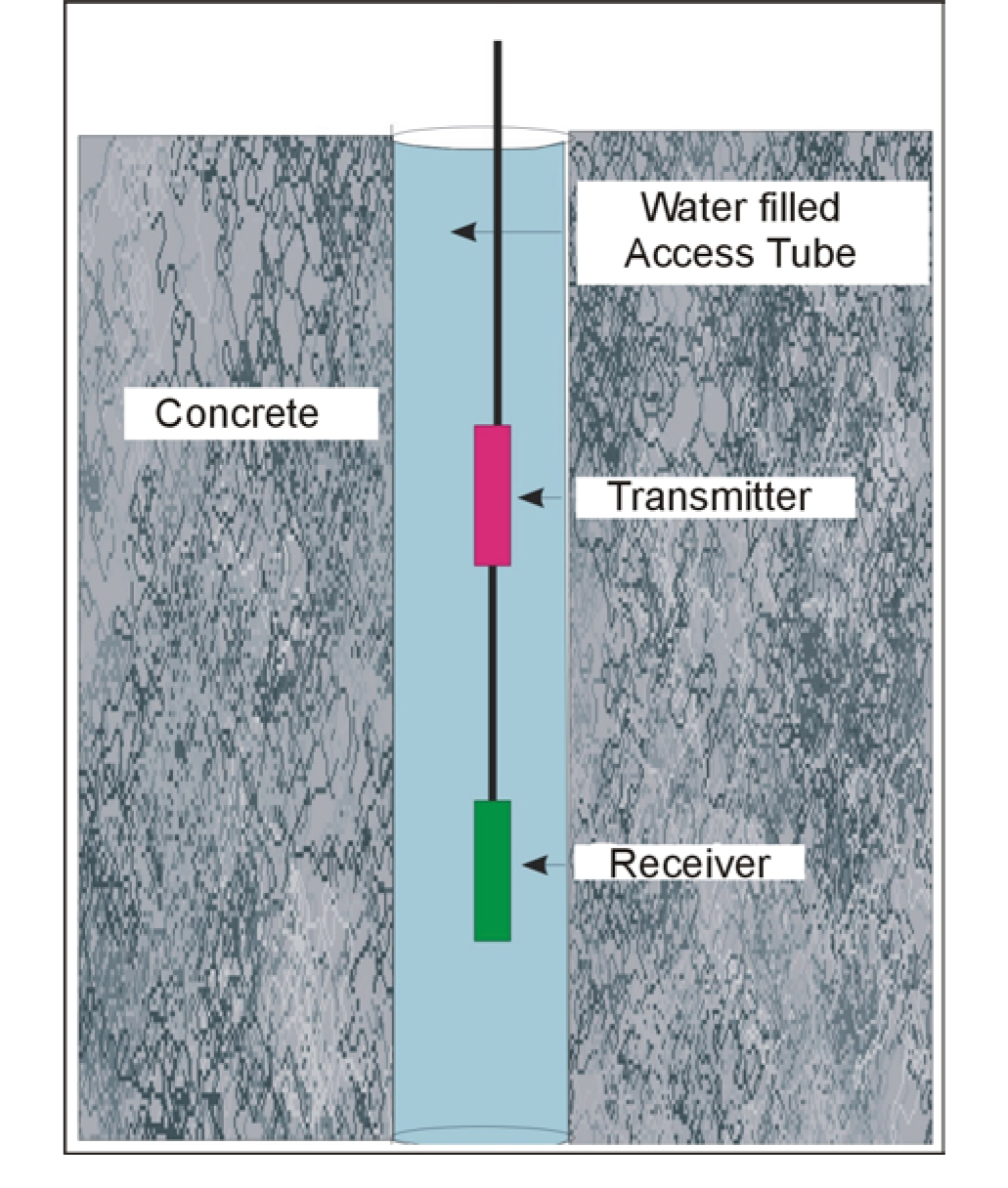
Figure 28. Single Hole Sonic Logging instrument.
Ultraseismic (US) Profiling
Ultraseismic (US) tests are performed to evaluate the integrity and determine the length of shallow and deep foundations. US tests can be performed on drilled shafts and driven or auger-cast piles. The test can also be performed on shallow wall-shaped substructures such as an abutment or a wall pier of a bridge provided at least 1.5 to 1.8 m of the side of the structural element are exposed for testing. The method is particularly useful in testing abutments and wall piers of bridges because of the relatively large exposed areas available for testing.
Ultraseismic tests can be performed on concrete, masonry, stone, and wood foundations. Steel pile foundations can also be tested, but damping of the energy in this case is much greater than that of concrete and wood due to the large surface areas and small cross-sectional areas of steel piles.
The Ultraseismic method was developed by Mr. Frank Jalinoos as part of NCHRP 21-5 research program in response to the difficulty encountered in interpreting the Sonic Echo/Impulse Response and Bending wave methods from complex structures (such as a bridge) where many reflecting boundaries are present. This method is an adaptation of multi-channel seismic reflection method to bounded engineered structures.
Basic Concept: The Ultraseismic method uses multi-channel, three-component (vertical and two perpendicular horizontal receivers, i.e., triaxial receiver) recording of acoustic data followed by computer processing techniques adapted from seismic exploration methods. Seismogram records are typically collected by using impulse hammers (experimented with 0.090, 0.453, 1.36, and 5.4-kg hammers) as the source and accelerometers as receivers that are mounted on the surface or side of the accessible bridge substructure at intervals of 30 cm or less. The bridge substructure element is used as the medium for the transmission of the seismic energy. Four wave modes of longitudinal (compressional) and torsional (shear) body waves as well as flexural (bending) and Rayleigh surface waves can be recorded by this method. Seismic processing can greatly enhance data quality by identifying and clarifying reflection events that are from the foundation bottom and minimizing the effects of undesired wave reflections from the foundation top and attached beams. For concrete bridge elements, useful wave frequencies up to 4-5 kHz are commonly recorded. This method can be used in two modes-one called Ultraseismic Vertical Profiling (VP), presented below, and the Horizontal Profiling Method (HP).
Data Acquisition: The Vertical Profiling test geometry is presented in figure 29 and shows the accelerometers and impact point. The impact point can be located either at the top or the bottom of the receiver line. Vertical impacts to the substructure are comparatively rich in compressional wave energy, although more flexural/Rayleigh (surface) wave energy is generated. Horizontal impacts are rich in flexural wave energy when the impacts generate wavelengths that are longer than the thickness of the substructure element. Impacts that generate wavelengths shorter than the thickness will be rich in Rayleigh wave energy. The VP lines are useful in differentiating downgoing events from the upgoing events based on their characteristic time moveout, and accurately measure their velocity. A VP line is also used to tie reflection events from the bottom to a corresponding horizon in a HP section. For a medium with a bounded geometry, such as a bridge column, four types of stress waves are generated, including longitudinal, torsional, surface (Rayleigh), and flexural (bending) waves. In longitudinal vibration, each element of the column extends and contracts along the direction of wave motion that is along the column axis. In torsional vibration, each transverse section of the column remains in its own plane and rotates about its center. Finally, in flexural vibration, the axis of the column moves laterally in a direction perpendicular to the axis of the column. Each wave type can independently provide information about the depth of the foundation or the presence of significant flaws within the bridge substructure. However, practically, longitudinal (P-wave, compressional) and flexural (bending) waves are much easier to generate on bridge substructures than torsional. Consequently, compressional and flexural wave energy was generated by orienting impacts to substructures vertically and horizontally, respectively.
Advantages: The Ultraseismic (US) method uses well-proven processing techniques developed in the seismic reflection exploration method. Multiple-channel recording allows for differentiation of bottom echoes from other complex wave modes far more reliably than single-channel Sonic/Pulse Echo or Bending wave methods.
US can be used for assessing the integrity of bridge foundations as well as columns, like determining the post-earthquake damage of steel-cased concrete columns. For wall structures, this method can be used to obtain two-dimensional reflection images containing defect zones.
Limitations: The strength of the echo depends on the surrounding soil, and the signal-to-noise ratio decreases as the length-to-diameter ratio of columnar shape structures exceeds 20 to 30. Defects below a large defect may be indistinguishable and defects near the bottom of the pile may be difficult to detect.
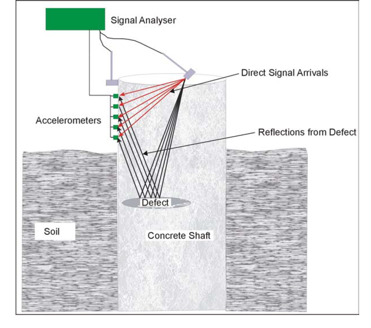
Figure 29. Ultraseismic test method showing the vertical profiling test geometry.
Thermal Integrity Profiling (TIP)
Thermal Integrity Profiling (TIP) is a down-hole concrete integrity test that monitors the heat of hydration as the concrete sets and cures. The test detects potential areas of soil intrusion, concrete contamination or segregation, significant neck-ins, or large bulges (bulbing).
TIP tests are sometimes performed in addition to, or in place of, crosshole sonic log tests in drilled shafts or augered, cast-in-place (ACIP) piles. TIP tests, with modified analysis procedures, can also be performed on diaphragm (slurry) wall structures.
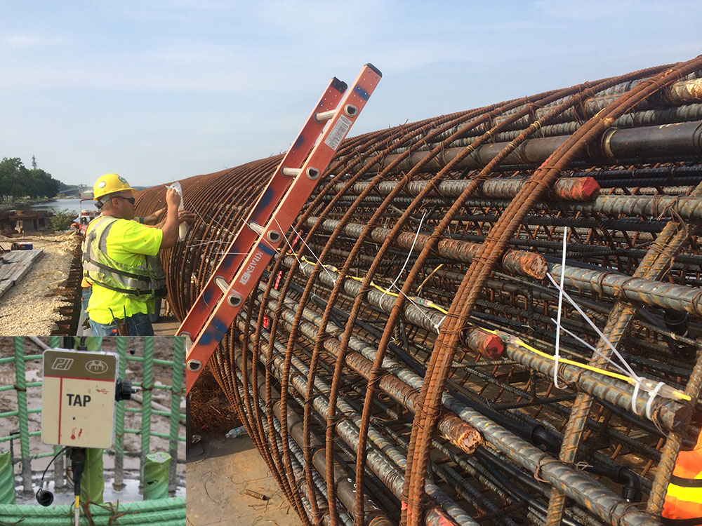
Basic Concepts: ASTM D7949, “Standard Test Methods for Thermal Integrity Profiling of Concrete Deep Foundations” covers two methods for collection of the temperature data – Method A, which uses an infrared temperature probe inserted in access tubes that have been pre-placed in the foundation, attached to the reinforcing cage, and Method B, which uses sacrificial thermal wires attached directly to the reinforcing cage. For either method, ASTM D7949 requires one temperature monitoring location per foot of diameter. Thus, a 6-foot diameter shaft would have six (6) tubes for Method A, or six (6) wires for Method B, equally spaced around the shaft perimeter, and extending down the full depth of the shaft. However, for practical and economic reasons, Method A is rarely used, and almost all specifications for TIP require Method B.
The thermal wires used for Method B have digitally-addressable temperature sensors spaced at 12-inch intervals vertically (Figure 29X). A Thermal Acquisition Port (TAP) is attached to each wire prior to concrete placement, to record the temperature from each sensor or “node” at preset intervals, typically every 15 minutes (Figure 29X, Inset). The TAP box starts recording temperature automatically when connected to the thermal wire.
With either Method A or Method B, monitoring is typically continued until the temperature “peaks,” or shows no significant further increase. The temperature data are then downloaded and processed via an automated analysis algorithm.
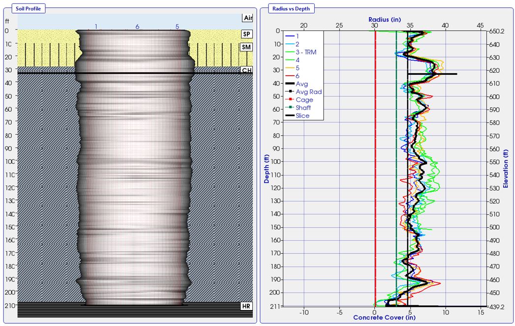
Data Processing: Using proprietary analysis and reporting software, the analyst inputs known or designed shaft, casing, and reinforcing cage dimensions, description or classification of soil strata, ambient air and soil temperature, and the number of measurement nodes per wire. The software then estimates shaft radius at each measurement node, thus building both a vertical profile of shaft temperature variations at any given time, and a profile of estimated shaft dimensions.
Data Interpretation: Concrete that has necked in due to soil intrusion, been contaminated with groundwater or sediment, or has segregated during placement, will have a lower temperature than the rest of the shaft, and the estimated radius profile will show an apparent reduction in cross-section. If the shaft has bulged, the extra mass of concrete outside the reinforcing cage will produce a higher temperature, and the estimated radius profile will show an increase in cross-section at that location. Similarly, if the cage is eccentric, the sensors closest to the exterior of the shaft will show lower temperatures, and the sensors closer to the center of the shaft will show higher temperatures. A example of TIP data presentation is shown in Figure 29Y.
Advantages: Because TIP testing works most effectively during the hydration process, it can usually be performed sooner than Crosshole Sonic Logging or other low strain integrity tests, thus expediting shaft evaluation and acceptance.
The TIP test is unaffected by shaft length/diameter ratio, and so can be used on long, slender shafts where other low-strain integrity tests would probably be inconclusive.
Limitations: Great care must be taken when installing the TIP wires on the reinforcing cage, and when picking and placing the cage in the excavation, to avoid damaging the wire or sensors. If a wire gets broken, no data will be collected from the zone below the break. Likewise, the TAP boxes must be protected during concrete placement.
Analysis of TIP data requires elevated concrete temperature. When hydration is complete and the concrete cools down, the TIP tests can no longer provide useful data. Therefore, retesting because of equipment or sensor malfunction, or to see if the concrete has improved with age, is not possible.