Basic Concept: In TDR, electrical pulses travel down the cable, and the reflected energy is recorded by the TDR instrument. Any impedance change, such as cable end or cable damage, will cause some energy to reflect back toward the TDR instrument where it is displayed. The method can also be used to detect bridge scour and monitor pier and abutment movement during flood events.
TDR is a relatively new method that appears to hold significant promise. However, it is not a typical geophysical method and is discussed here because of its apparent potential and importance in detecting scour.
TDR uses electromagnetic impulses that travel along a cable and are reflected when they encounter an impedance change. This can occur at the end of the cable or at a break or imperfection. The TDR instrument measures the time that the signal takes to travel along the cable and return to the instrument. Knowing the speed of travel of the wave then allows the traveled distance to be calculated.
Cables that can be used with the TDR method are illustrated in figure 47.
In the case where two cables are shown an impedance occurs between the two
central conductors. The second example in figure 47 is called a coaxial cable
and consists of a central conductor surrounded by a dielectric medium and
then a second conductor.
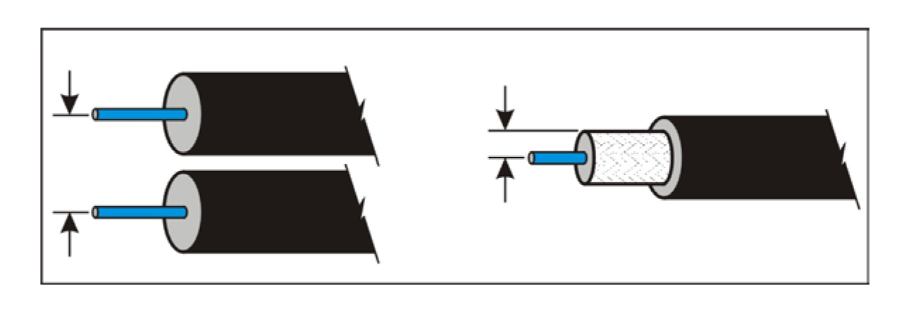
Figure 47. Cable configurations for use in the Time Domain Reflectometry method.
TDR instruments detect reflections from the cable ends or imperfections in the cable, as described above. Figure 48 shows the TDR signals from the ends of the cable and an imperfection in the center of the cable.
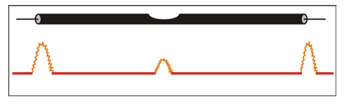
Figure 48. Time Domain Reflectometry signals from cable ends and a thinner section of the cable.
Data Acquisition: For the TDR method, the survey design is essentially the design of the cable placement. Once the cable is in place, monitoring will begin, searching for TDR reflections that might indicate scour depth or pier movements in flood conditions.
Measurements of scour at bridges founded on shallow footings indicate maximum scour occurs around the upstream side of footings during floods. As scour progresses and soil deposits are eroded, footings may be exposed and eventually undermined, leading to intolerable pier movement. Optimal placement of TDR cables would, therefore, be through the footing section on the upstream side. Most importantly, the cable monitoring system must operate at high water flows when footing and pier displacement is most likely to occur as a result of scour.
Although bridge abutments may be less affected by scour, under certain circumstances they may need to be monitored for detrimental movements. Abutments and piers can be inspected using the same system designed to measure very small structural movements (on the order of 2 mm) relative to their foundation materials. Detection of such small displacements should provide an early warning of progressive movements that may reduce the stability of the bridge.
Several cable installation schemes have been investigated for monitoring pier movement, but the most practical orientation of TDR cables is illustrated in figure 49.
A single cable is shown extending from an accessible location on or below the bridge deck, down along the pier, and into a hole drilled through the footing and foundation materials. The cable must be encased in grout through the hole to ensure direct transfer of soil-structure displacements. In addition, the cable should be enclosed by a protective pipe along the entire length of the pier to screen the cable from debris and weather. A more durable transmission line can be connected to the monitoring cable at the top of the pier and extended to the electronics.
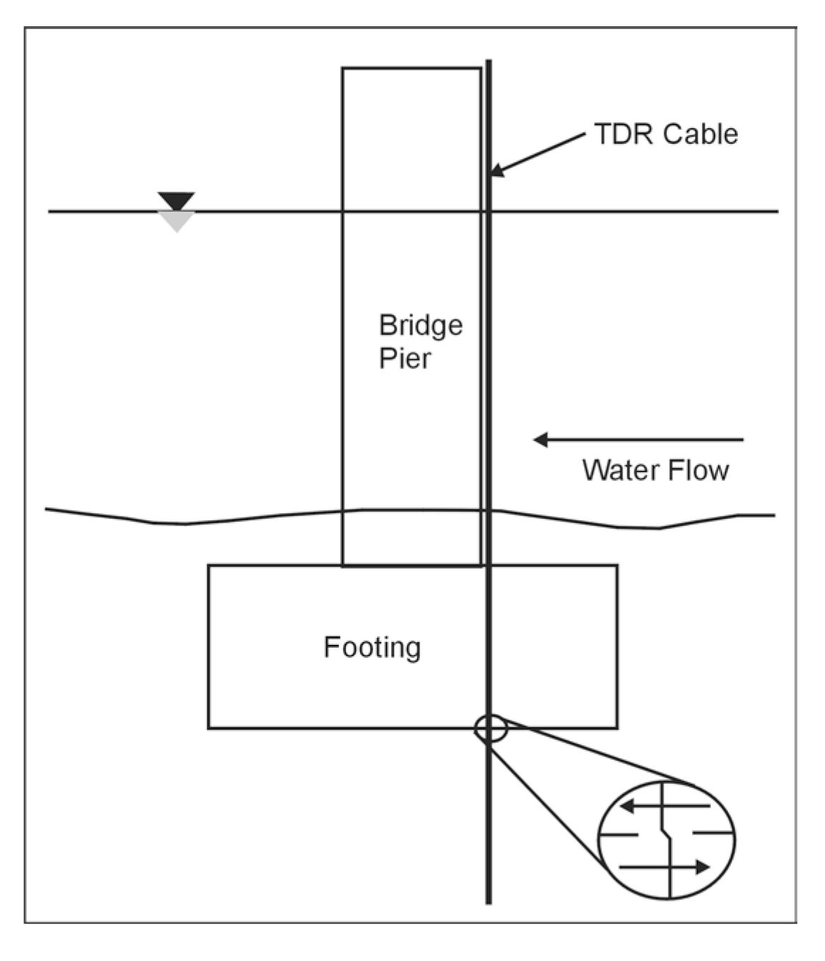
Figure 49. Cable installation for Time Domain Reflectometry measurements at a pier.(Dowding, et al. 1995)
The number and arrangement of TDR cables installed on an individual bridge pier will depend on many factors, including the scour-critical classification, risk associated with structural collapse, and installation and monitoring costs, among others. It is expected that a TDR system can be installed on new bridges, since cables can be easily incorporated into new construction. However, the complexity and cost of cable installation on existing bridges are significantly greater, and installation techniques to minimize these problems are currently being researched.
Data Interpretation: Pier footing movements can be detected from voltage reflections generated by local cable deformation. For instance, lateral translation or rotation of the footing would locally shear the cable-grout composite at the interface of the footing and foundation soils, as illustrated in figure 49. A minimum cable deformation of 2 mm produces a distinguishable voltage reflection in the TDR signal. Further footing displacement progressively shears the cable and produces increasingly larger voltage reflections at that point along the cable.
To accurately measure these structural displacements, the cable and grout must be sufficiently weak to deform under the applied loads. A special cable-grout system is currently being developed to measure localized soil deformation in earth structures. This development involves the design and production of an integrated cable and grout composite that exhibits low shear strength and compliance to deform uniformly with soft soils. In addition to embankments and excavations, this system can also be applied to monitor movements of footings or abutments founded on soft soils.
Advantages: A TDR measurement system provides several advantages for long-term monitoring of bridges. Previous deployment of TDR-based instrumentation suggests that it is robust enough to withstand emplacement during heavy construction and should perform during potentially damaging conditions such as floods and earthquakes. A miniaturized, low power, intelligent TDR pulser is currently being developed for remote monitoring. This signal pulsing and recording instrument is designed to reduce the size, complexity, and cost of current cable testing electronics. Remote access to multiplexed cables can be achieved with current electronics and existing telecommunication lines. These advantages would allow a survey of all bridge supports be performed remotely through one central unit, saving time and reducing costs.
Limitations: TDR cables are sometimes difficult to install, subject to damage, and accuracy of the TDR signal is reduced with increasing cable length.