Two- and three-dimensional tomography is used for the high resolution imaging of the subsurface between boreholes.
Basic Concept: Tomography is an inversion procedure that provides for two- or three-dimensional (2-D and 3-D) velocity (and/or attenuation) images between boreholes from the observation of transmitted first arrival energy.
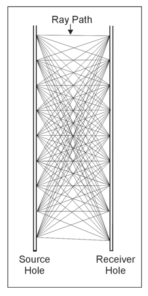
Data Acquisition: Tomography data collection involves scanning the region of interest with many combinations of source and receiver depth locations, similar to medical CAT scan (Figure 101). Typical field operation consists of holding a string of receivers (geophones or hydrophones) at the bottom of one borehole and moving the source systematically in the opposite borehole from bottom to top. The receiver string is then moved to the next depth location and the test procedure is repeated until all possible source-receiver combinations are incorporated.

Figure 101. Source and receiver locations for a tomographic survey.
Data Processing: In the tomographic inversion technique, the acoustic wavefield is initially propagated through a presumed theoretical model and a set of travel times are obtained by ray-tracing (forward modeling). The travel time equations are then inverted iteratively in order to reduce the root mean square (RMS) error between the observed and computed travel times. The inversion results can be used for imaging the velocity (travel time tomography) and attenuation (amplitude tomography) distribution between boreholes.
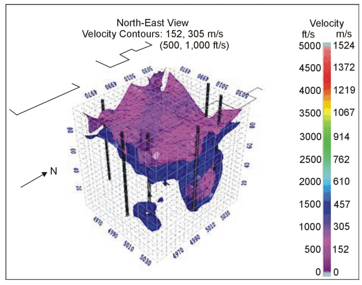
Data Interpretation: An example of a cross borehole tomography survey to investigate an active sinkhole causing damage to property in a residential neighborhood in central Florida is shown below.
Figure 102 represents an isometric view of a low velocity zone defining the sinkhole. The surficial feature at approximately 8 meters depth is clearly visible. Also the "throat" of the sinkhole, at a depth of approximately 24 meters, indicates the presence of an opening in the confining layer. This is verified by the absence of a solid clay zone above the refusal material within a boring performed at the sinkhole.

Figure 102. Isometric view of the low velocity zone. (NSA Geotechnical Services, Inc.)
Advantages: Tomography provides for a high-resolution two-dimensional area or three-dimensional volumetric imaging of target zones for immediate engineering remediation. Tomography can then be used in "before and after surveys" for monitoring effectiveness of remediation. Tomography can also be used in "before and after surveys" for monitoring fluid injections between test holes or for assessing the effectiveness of soil improvement techniques.
Attenuation tomography can be used for the delineating fracture zones. Wave equation processing can be used for a high-resolution imaging of the reflection events in the data including those outside and below the area between the boreholes.
Limitations: Tomography is data-intensive and specialized 3-D analyses software is required for true three-dimensional imaging. Artifacts can be present due to limited ray coverage near the image boundaries.