Basic Concept: Ground Penetrating Radar (GPR) can be used to locate shallow cavities. However, depth of penetration is very dependent on the site conditions, in particular on the resistivity of the ground and clay content. Best results will be obtained in unsaturated areas where no clay is present. For voids at depth, the most serious issue is penetration. Therefore, an antenna with a sufficiently low frequency to penetrate to the required depth is needed.
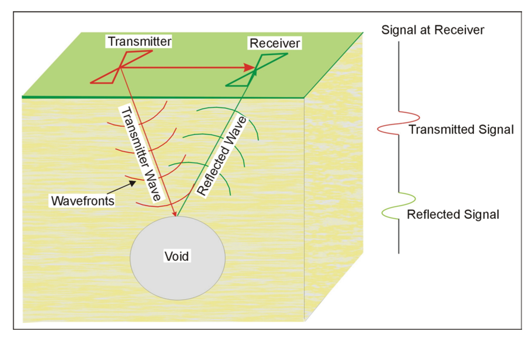
The GPR instrument consists of a recorder and a transmitting and receiving antenna, with different antennae being used to provide different frequencies. The transmitter provides the high-frequency (25 MHz to 1,500 MHz) electromagnetic signals that penetrate the ground and are reflected from objects and boundaries that have a different dielectric constant from their host material. The reflected waves are detected by the receiver and stored in memory. The transmitter and receiver antenna and the GPR waves are illustrated in figure 87. An air-filled void will almost certainly provide a dielectric contrast with the host rocks. It is also possible that a water-filled void may provide a dielectric contrast with the host rocks.

Figure 87. Ground Penetrating Radar system over a void.
Several companies manufacture GPR equipment, including Geophysical Survey Systems Inc, (GSSI), GeoRadar, Mala GeoScience, and Sensors and Software. Figure 112 shows a typical controller manufactured by GSSI and includes the data recorder and system control for a GPR system.
Any antenna supported by this instrument can be attached and used to collect data. Figure 113 shows a 100 MHz antenna that can be used with the above instrument. The 100 MHz antenna is suited for deeper applications to depths of about 20 m and could be used to locate cavities.
Data Acquisition: GPR surveys are conducted by pulling the antenna across the ground surface at a normal walking pace. The recorder stores the data as well as presenting a picture of the recorded data on a screen. When conducting GPR surveys, it is usually advisable to have a selection of antennae available and to perform tests to ascertain the most appropriate antenna to use for the survey.
Data Processing: It is possible to process the data, much like the processing done on single channel reflection seismic data. Processing might include distance normalization, horizontal scaling (stacking), vertical and horizontal filtering, velocity corrections, and migration. However, depending on the data quality, this may not be necessary since the field records may be all that is needed to observe the cavity.
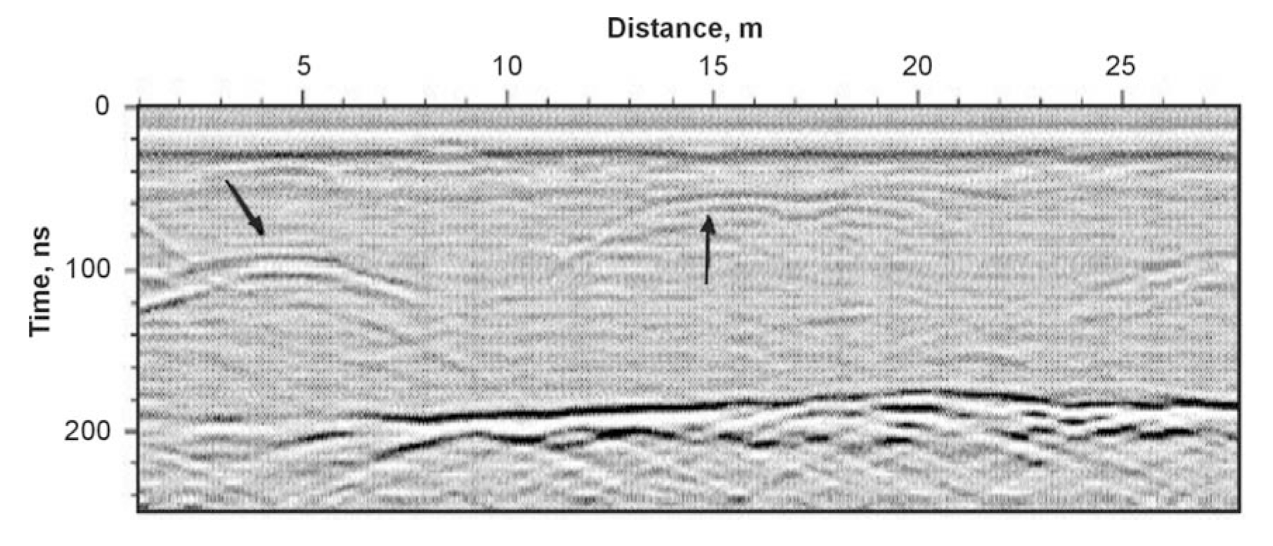
Data Interpretation: To calculate the depth to the cavity, the speed of the GPR signal in the soil or rock at the site needs to be obtained. This can be estimated from ts showing speeds for typical soil/rock types or it can be obtained in the field by conducting a small traverse across a buried feature whose depth is known. A typical GPR record over voids (cavities) is shown in figure 3. The arrows show the reflectors thought to indicate voids.

Figure 88. Ground Penetrating Radar data showing reflections thought to indicate voids.
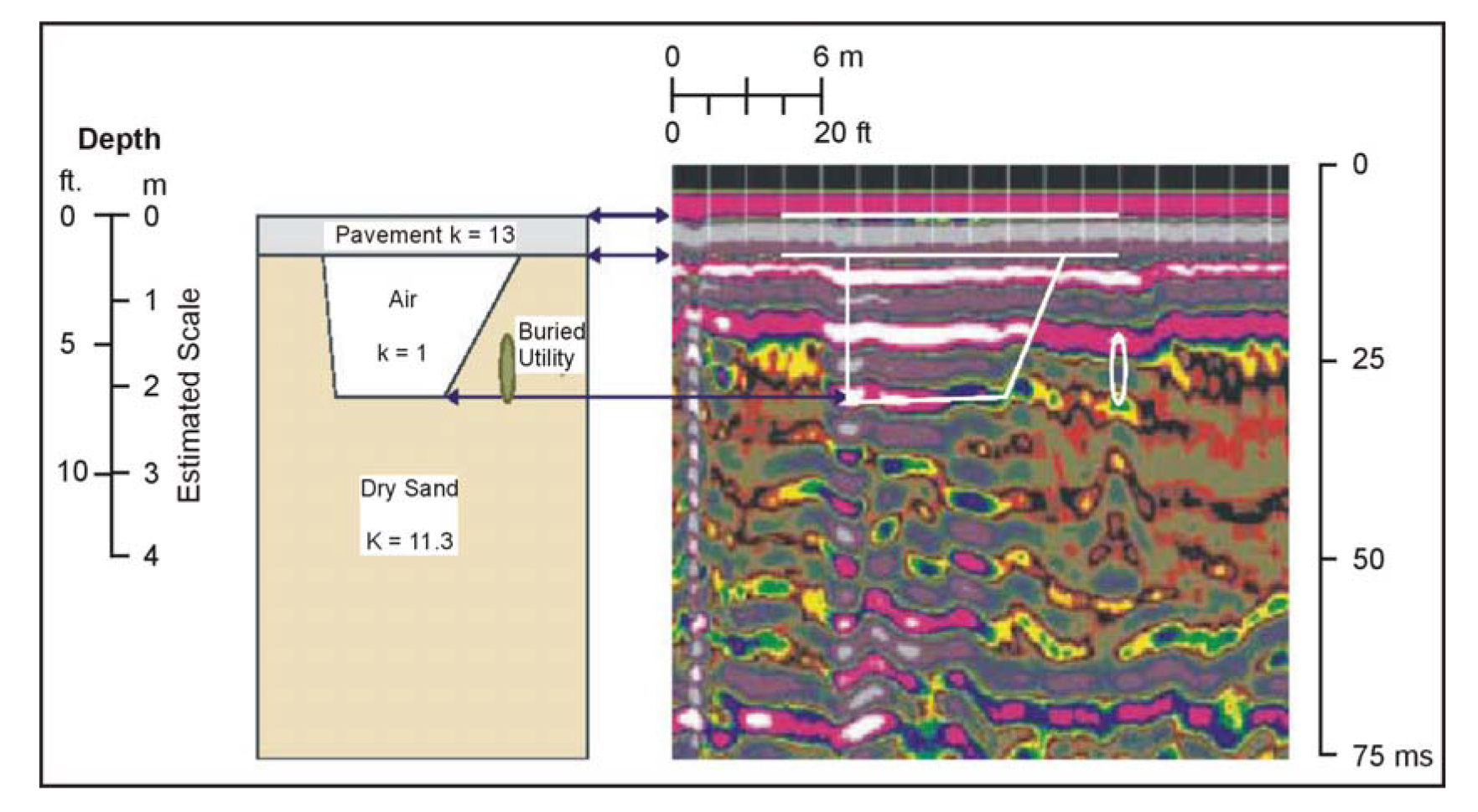
Figure 89 shows GPR data from a pavement survey showing voids under the pavement, along with the geologic, structural interpretation.

Figure 89. Ground Penetrating Radar data from a pavement survey showing its interpretation. (Hauser, et al. 2001)
Advantages: GPR data can be recorded quickly and the data is presented on a screen during the survey allowing its quality to be evaluated. If the resolution or penetration depth are not appropriate then the antenna frequency can be changed.
Limitations: Probably the most limiting factor for GPR surveys is that their success is very site specific and depends on having a contrast in the dielectric properties of the target compared to the host overburden along with sufficient depth penetration to reach the target. Penetration of the GPR signal may be severely limited in saturated, electrically conductive ground containing clay. For shallow surveys along roads, saline conditions resulting from de-icer may produce conductive conditions. In addition, any metal reinforcement and other features, such as guardrails and power lines, may hinder a survey. However, it is likely that most cavities will provide the desired dielectric contrast needed; thus, depth of penetration is probably the most important factor. Dielectric contrasts will be greater with an air-filled void and least with a void filled with alluvium or water. Lower frequency GPR antennae are usually not shielded, allowing GPR energy to radiate in all directions. Thus, surveys under bridges or other structures using lower frequency antennae will produce reflections from these overhead features that may interfere with reflections for subsurface features. It may be possible to separate the reflection from the bridge deck or other overhead features from subsurface reflections, providing these two reflection times are significantly different.